Figure 4.3: Critical path in ns.
The techniques presented in Chapter 3 are applied to the case of a double-precision radix-4 division unit, which is typical of those found in many floating-point processors.
The algorithm and the basic implementation of the radix-4 division has been already presented in Section 3.1.
We indicate with std the implementation of the basic radix-4 divider shown in Figure 3.1 at page pageref. The critical path, shown in Figure 4.3, is 7.0 ns. It is computed post-layout and takes into account the RC-effect of interconnections.

Figure 4.3: Critical path in ns.
This first implementation, optimized for minimum delay, has the energy dissipation characteristics shown for std in Table 4.1 in page pageref at the end of this section. The largest part of the energy is consumed in the registers and in the convert-and-round unit.
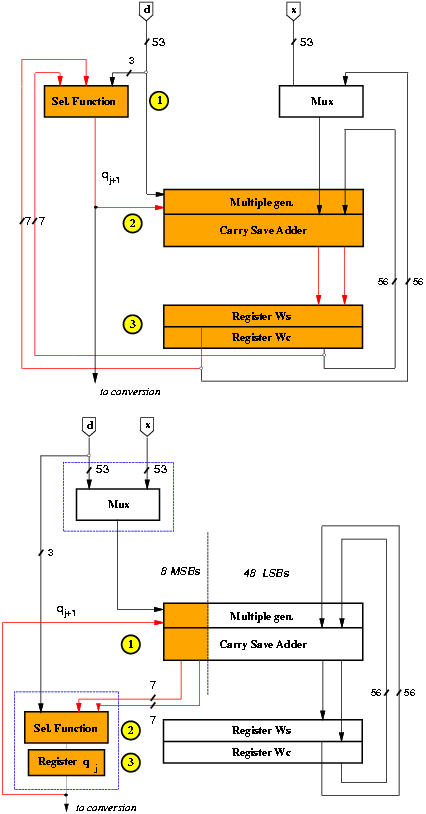
The retiming is done by moving the selection function from the first part of the cycle to the last part of the previous cycle (Figure 4.4). The reduction in the number of transitions in the recurrence for the retimed implementation is 15% with respect to the std.

Figure 4.4: Retiming of recurrence.
The critical path is now limited to the 8 most-significant bits, so that the 48 least-significant can be redesigned for lower power dissipation by changing the redundant representation of the residual, using low-drive gates and dual voltage. Note that, although only 7 bits are required for the selection function, since the representation is in carry-save form, the eighth bit in the recurrence produces the least-significant carry to go in the selection function.
Furthermore, by eliminating buffering for the 8 most-significant bits in the critical path in MULT, we can reduce the critical path (see Figure 3.5 at page pageref). However, the load connected to the output of register qj+1 is larger (320%) and the delay in the register is increased by about 30% reducing the benefits of this modification. The overall improvement in delay is 0.3 ns corresponding to less than 5% of the critical path.
After the retiming, the multiplexer can be moved out of the recurrence.
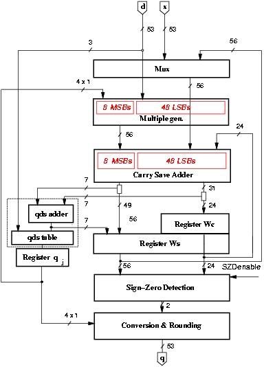
The change in the redundant representation is done using a radix-4 carry-save representation with two sum and one carry flip-flops for each two bits (Figure 4.5). Since this requires a redesign of the carry-save adder to propagate the carry of the even bit-slice to the next bit-slice, in order not to increase the critical path this is done only in the 48 least-significant bits of w[j]. This modification results in a reduction of 25% in the number of flip-flops for the bits not in the critical path. Figure 4.6 shows that the 7 MSBs of the carry-save representation of w[j+1] are assimilated in qds adder, and by storing the assimilated value for these 7 bits, we can eliminate the corresponding flip-flops in register Wc. The number of flip-flops in register Wc decreases from 56 to 25.

Figure 4.5: Radix-4 implementation in the carry-save adder.

Figure 4.6: Block diagram of
In the retimed recurrence, we can use lower drive capability gates for the 48 least-significant bits (LSBs) of the multiple generator and the carry-save adder.
By equalizing the paths of the input signals of the blocks we reduce the generation of glitches. The equalization is done by delaying the clock to registers Ws and Wc, as previously explained in Figure 3.11 at page pageref.
The use of automatic floor-planning in the placement and routing of standard cells limits the control on the interconnection delay, and the difference in the delays generates glitches. Therefore, the reduction of the spurious transitions is quite small, and this reflects on the energy dissipation that is reduced by less than 5%.
The combination of these techniques results in implementation rec. The actual reduction in the recurrence is about 20% with respect to std (Table 4.1 in page pageref).
As mentioned in Section 3.11, the SZD is only used in the rounding step and it can be switched off by forcing a constant logic value at its inputs during the recurrence steps.
The total energy dissipated in the convert-and-round unit is 30% of rec.
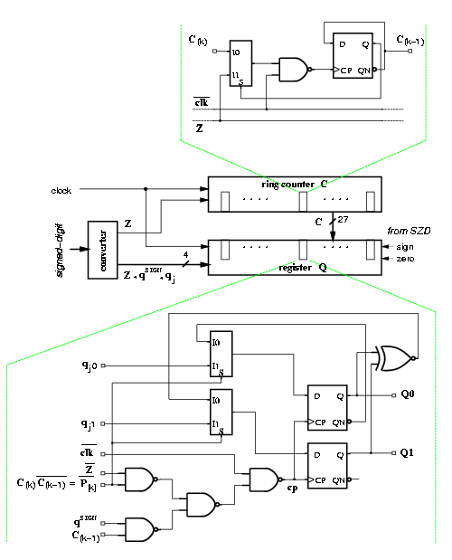
In the implementation of the modified algorithm (Figure 4.7), described in Section 3.10, we obtained a reduction of the energy dissipation for the convert-and-round unit of about 55%, However, more than 50% of the total energy in the unit was dissipated in the trees to distribute the clock, and the other signals to the array of flip-flops. By implementing gated-trees we obtained a reduction of about 65% in the block.

Figure 4.7: Convert-and-round unit for radix-4 divider.
This final implementation of the convert-and-round unit and its integration in the whole divider corresponds to l-p. With respect to the basic implementation std we reduced the energy dissipation by 40% (Table 4.1 in page pageref).
In order to evaluate the possible lower voltage V2 to be used in a dual voltage implementation we need to determine the time slack available for the LSBs in the recurrence. The delay of the least-significant portion depends on the type of CSA adder used, since the delay of the radix-4 CSA is larger than that of the radix-2 CSA. By implementing the LSBs of the recurrence with radix-2 CSAs, the delay in the LSBs is 3.1 ns, resulting in a time slack of 3.9 ns. In this case V2 = 2.0 V can be chosen without affecting the latency of the divider. On the other hand, by opting for the use of radix-4 CSAs, the time slack is reduced to 3.0 ns and, consequently, V2 can be lowered to 2.2 V. The same estimated values for Ediv are obtained by applying expression (4.3), so that the radix-4 CSA solution might be preferred because of the smaller area. Only two level-shifters (low to high) are needed (Figure 3.10, page pageref).
In the convert-and-round unit, unlike in the case of the recurrence, the number of required level shifters is quite high (53), but each bit can switch at most twice. Furthermore, the additional delay due to the low-voltage cells in the rounding cycle might increase the critical path. However, we roughly estimated that the energy dissipated could be halved with respect to l-p. Entry d-v in Table 4.1 represents an estimation of a possible implementation with low-voltage gates. The energy reduction with respect to the basic divider is about 60%.
The first approach was to synthesize with Synopsys Design Compiler the RT-level VHDL description of a fairly complex circuit as the recurrence portion of the radix-4 divider. The timing constraints were set accordingly to the relation between the critical path obtained for the implementation of Section 4.2 with Passport/COMPASS (7.0 ns) and the ratio between the speed of the two libraries (0.67). The resulting timing constraint of 5.0 ns for the critical path was not met (7.0 ns) in the synthesis with Design Compiler. The critical path of the resulting circuit is compared in Figure 4.8 with the one obtained with Passport/COMPASS. Note that the critical path for the implementation with Passport/COMPASS was not obtained by synthesis of the whole RT-level model, but by manual design of the blocks in the recurrence with the exception of the selection function that was synthesized stand-alone using COMPASS ASICSynthesizer.

Figure 4.8: Critical path for implementations with
After having obtained the fastest possible circuit with Synopsys we optimized the power with Power Compiler. Results showed a reduction in the power dissipated of about 7% with a small increase in the critical path (2%).
Then, we synthesized the RT-level VHDL description of the retimed recurrence and we got a better reduction in power dissipation (about 10%) and a shorter critical path (5.9 ns), but still the timing constraints were not met.
In conclusion, for larger and fairly complex circuits not only the power is not reduced much, but also the initial design, optimized for smaller delay, is not as good as attainable by manual design. For this reasons, we decided to use Synopsys Power Compiler only to optimize the energy dissipation of small blocks, as described next.
The second approach was to use the same methodology used for the design with COMPASS: manual design of the large regular blocks and synthesis of selection function and other small irregular blocks.
The synthesis of the selection function stand-alone was more satisfactory and showed a critical path of 3.0 ns (critical path for SEL in Passport/COMPASS implementation is 4.0 ns). The power reduction, obtained by incremental compilation with power dissipation constraints, was of about 20%, without affecting the delay.
In Table 4.1, the columns labeled syn represent an estimate of the units derived from l-p and d-v in which the selection function was optimized with Power Compiler.
Table 4.1 summarizes the result obtained in the low-power optimization of the radix-4 divider. Each column represents a different implementation. Values in boldface indicate a variation from the previous value. Entry std refers to the standard implementation, optimized for speed, entry rec is obtained from std by applying low-power techniques to the recurrence portion, and entry l-p is rec with the low-power conversion and rounding. Entry d-v is an estimate of a possible implementation with dual voltage, and entries syn indicate the improvements attainable with Synopsys Power Compiler optimization. In columns syn only variations in SEL are indicated.
| std | rec | l-p | syn | d-v | syn | ||||||||||||||||||||||||||||||||||||||||||||||||||||||||||||||||||||||||||||||||
| blocks | nJ | nJ | nJ | (est.) | (est.) | (est.) | |||||||||||||||||||||||||||||||||||||||||||||||||||||||||||||||||||||||||||||||
| control | 1.1 | 1.1 | 1.1 | 1.1 | 1.1 | 1.1 | |||||||||||||||||||||||||||||||||||||||||||||||||||||||||||||||||||||||||||||||
| clk tree | 0.9 | 0.9 | 0.9 | 0.9 | 0.9 | 0.9 | |||||||||||||||||||||||||||||||||||||||||||||||||||||||||||||||||||||||||||||||
|
mux | 1.1 | 0.3 | 0.3 | 0.3 | |||||||||||||||||||||||||||||||||||||||||||||||||||||||||||||||||||||||||||||||||
| mul. gen. | 3.6 | 2.8 | 2.8 | 1.9 | |||||||||||||||||||||||||||||||||||||||||||||||||||||||||||||||||||||||||||||||||
| CSA | 5.9 | 4.8 | 4.8 | 2.2 | |||||||||||||||||||||||||||||||||||||||||||||||||||||||||||||||||||||||||||||||||
| sel. func. | 1.3 | 1.6 | 1.6 | 1.2 | 1.6 | 1.2
|
register Ws | 6.4 | 6.4 | 6.4 | | *4.0 |
|
register Wc | 6.2 | 3.5 | 3.5 | | 2.0 |
|
register q | - | 0.3 | 0.3 | | 0.3 |
|
total recur. | 24.5 | 19.5 | 19.5 | 19.0 | 12.0 | 11.5
|
|
| SZD 5.7 | 5.7 | 0.6 | | 0.6 |
|
conv-round unit | 13.2 | 13.2 | 3.9 | | *1.4 |
|
| total C&R 19.0 | 19.0 | 4.5 | 4.5 | 2.0 | 2.0
|
|
| Total divider 45.5 | 40.5 | 26.0 | 25.5 | 16.0 | 15.5
|
| Ratio 1.00 | 0.90 | 0.60 | 0.55 | 0.35 | 0.33 |
| Values marked * include level shifters
| | ||||||||||||
The delay of the divider is not changed because the retiming did not increase the critical path and other modification that affected delay were done for parts in the unit not in the critical path. As for the area, we have a reduction of about 20% between std and l-p. This is mainly due to the change in the redundant representation of w[j] and in the new convert-and-round unit. In both cases we eliminated flip-flops, about 25% of the total. We estimated that an optimization with Synopsys Power Compiler could reduce the energy dissipation by an additional 5%.
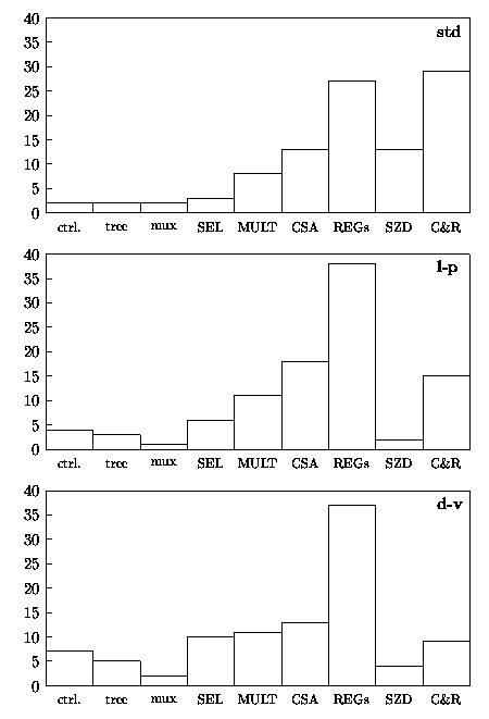
Figure 4.9 shows the breakdown, as a percentage of the total, of the energy dissipated in the main blocks composing the unit.

Figure 4.9: Percentage of energy dissipation in radix-4 divider.