Tunable Floating-Point Multiplier
Alberto Nannarellii
DTU Compute, Technical University of Denmark
Kongens Lyngby, Denmark
Email: alna@dtu.dk
Abstract
In this report, we address the design of a multiplier in Tunable
Floating-Point (TFP) precision for use in
on-chip accelerators.
The precision can be chosen for a single operation by selecting a specific number of bits for significand and exponent in
the floating-point representation.
By tuning the precision of a given algorithm to the minimum precision achieving
an acceptable target error, we can make the computation more power efficient.
1 Introduction
In this work, we address the design of an on-chip accelerator with Tunable
Floating-Point (TFP) precision.
That is, the precision of operands and results can be chosen for a
single operation by selecting a specific number of bits for significand and
exponent in the floating-point representation.
By tuning the precision of a given algorithm to the minimum precision achieving
an acceptable target error, we can make the computation more power efficient.
In this work, we focus on floating-point multiplication, which is the more power
demanding arithmetic operation.
We present a Tunable Floating-Point multiplier (TFP-mult)
which can be used as part of on-chip accelerators.
The TFP-mult can handle significand
precision from 24 to 4 bits, and exponent from 8 to 5 bits.
The maximum precision (m=24, e=8) is that of binary32 (single-precision), and the tunable
range includes binary16, or half-precision, (m=11, e=5).
The main features of the TFP multiplier are:
- Providing correct rounding when reducing the precision of the significands.
-
The precision of the significand m and the exponent range e can be
changed on a cycle basis.
The goal is to obtain a power efficient multiplier by trading off
accuracy (precision) and energy.
2 Tunable Floating-Point
The floating-point representation of a real number x is
|
x = (−1)Sx ·Mx ·bEx x ∈ ℜ |
|
where Sx is the sign, Mx is the significand or mantissa (represented
by m bits),
b is the base (b=2 in the following), and Ex is the exponent
(represented by e bits).
The representation in the IEEE 745-2008 standard [1] has
significand normalized 1.0 ≤ Mx < 2.0 and biased exponent:
bias = 2e−1−1.
The formats for binary floating-point in IEEE 745-2008 are specified in
Table 1 [1].
| Binary formats |
|---|
| Format | binary16 | binary32 | binary64 | binary128 |
|---|
| Storage (bits) | 16 | 32 | 64 | 128 |
| Precision m (bits) | 11 | 24 | 53 | 113 |
| Total exponent length e (bits) | 5 | 8 | 11 | 15 |
| Emax | 15 | 127 | 1023 | 16383 |
| bias | 15 | 127 | 1023 | 16383 |
| Trailing significand f (bits) | 10 | 23 | 52 | 112 |
|
Table 1: Binary formats in IEEE 754-2008 [
1].
For example, for binary32 (m=24, e=8)
|
DRb32 = (224−1)228−1 ≈ 9.7 ×1083 |
|
which is much larger than the dinamic range of the 32-bit fixed-point representation:
DRFXP = 232−1 ≈ 4.3 ×10⁹ [2].
For the Tunable Floating-Point (TFP) representation, we only consider dynamic ranges
from and below the binary32 representation. We support significand's
bit-width from 24 to 4 and exponent's bit-width from 8 to 5.
Table 2 shows the dynamic ranges for some TFP cases.
| | | | storage | |
|---|
| m | e | DR | bits∗ | comment |
|---|
|
| 24 | 8 | 9.7 ×1083 | 32 | binary32 |
| 11 | 8 | 1.2 ×1080 | 19 | |
| 4 | 8 | 8.7 ×1077 | 12 | |
|
| 24 | 5 | 3.6 ×10¹⁶ | 29 | |
| 11 | 5 | 4.4 ×10¹² | 16 | binary16 |
| 4 | 5 | 3.2 ×10¹⁰ | 9 | |
|
| 16 | 65,536 | 16 | 16-bit FXP |
|
|
| ∗ It includes the sign bit. |
|
Table 2: Dynamic range for some TFP formats.
By comparing TFP with FXP ranges, the TFP ones are much larger than the FXP for
similar bits of storage. This is advantageous especially for multiplication
for which the dynamic range increases quadratically.
As for the significand's precision, the optimal bit-width depends on the application.
We assume that the TFP representation is normalized to have the conversions
compatible with the IEEE 754-2008 standard. Therefore, the implicit (integer)
bit is not stored. Subnormals support is quite expensive
for multiplication, and, therefore, we opted to flush-to-zero TFP numbers when
the exponent is less than −(Emax−1).
As for the rounding, TFP supports three types:
- RTZ Round-to-zero (truncation);
- RTN Round-to-the-nearest where half ulp2 is always added before the rounding;
- RTNE Round-to-the-nearest-even (on a tie) which is the default mode roundTiesToEven in IEEE 754.
3 TFP Multiplier
3.1 Baseline FP Multiplier
The starting point is a generic floating-point multiplier.
The architecture of the significand computation is sketched in
Figure 1.
We assume the FP-operands to be normalized and subnormals are flushed to zero.
The implicit (integer) bit is already included in Figure 1.
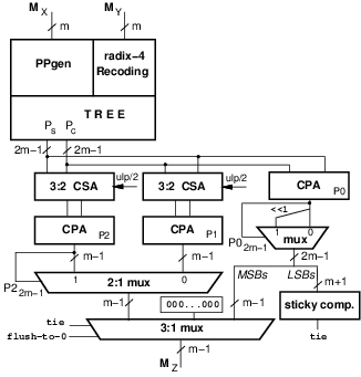
Figure 1: Significand computation in FP multiplier (for binary32 m=24).
Figure 2: Speculative rounding for m-bit significands.
To support roundTiesToEven, we need to compute the sticky bit
For each of the cases in Figure 2, if L=0, T=0 and R=1
the bit to be added for rounding is 0.
To include this case of rounding, we need to include a third adder which adds
PS+PC (CPA P0 in Figure 1).
Moreover, if the biased exponent is 0 (subnormal or zero) or 2e−1 (infinity), we need to flush the signicand to zero.
The final selection of the significand is done taking into account the leading
one in P2 (or P0), the roundTiesToEven condition tie and the exponent flag
flush-to-0.
The architecture of Figure 1 can be optimized by sharing parts of
the datapaths (addition of the m−1 least-significant bits, LSBs) and by using
compound adders [2], or by many other methods in the literature
[3].
The hardware to compute the exponent is sketched in Figure 3.
It consists in the exponents addition
followed by the speculative increment E2=E1+1 in case the
significand needs normalization (P2(47)=OVF=1).
In parallel to the exponent addition, the implicit bit is computed:
Mi(m)=0 if Ei=0.
To ensure the exponent is in the allowed range, E1, or E2, is checked against 0 and Emax.
The final exponent Ez is set depending on the signals INFTY (infinity) or ZERO (zero and subnormals), and, for the significand selection:
The sign is computed by a simple XOR-gate:
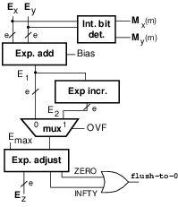
Figure 3: Exponent computation in FP multiplier (for binary32 e=8).
3.2 Hardware Support for Tunable FP
In this section, we explain how to augment the unit of Figure 1 and
Figure 3 to support TFP.
For the significand computation, the challenge is to inject the rounding bit in
position r so that the m resulting bits of the significand are correctly
rounded.
For example, as illustrated in Figure 4, for the
datapath of Figure 1 (the MSB of P2 is 47 for binary32),
if the required precision is m=11,
the rounding bit is in position
r=36 if the leading one in P2 is in position 47.
| pos. | 47 | 46 | 45 | 44 | 43 | 42 | 41 | 40 | 39 | 38 | 37 | 36 | 35 | 34 | 33 | … | 25 | 24 | 23 | 22 | … |
| P2: | 1 | b | b | b | b | b | b | b | b | b | L | R | b | b | b | … | 0 | 0 | 0 | 0 | … |
| RW: | 0 | 0 | 0 | 0 | 0 | 0 | 0 | 0 | 0 | 0 | 0 | 1 | 0 | 0 | 0 | … | 0 | 0 |
|
| SB: | - | - | - | - | - | - | - | - | - | - | - | - | - | - | - | … | - | L | R | b | … |
Figure 4: Example of "rounding word" (RW), and selection (SB) for sticky-bit computation for m=11.
This mask can be generated by the decoder. For example for m=11:
    RW:    0000 0000 0001 0000 0000 0000

    MASK:  1111 1111 1110 0000 0000 0000
The modified datapath supporting TFP m=[4,24] for significand computation is
depicted in Figure 5. The added or modified parts are in color
in the figure.

Figure 5: Significand computation to support TFP multiplication.
|
B6 = |
e1 + e0
|
, B5 = |
e1 ⊕e0
|
, B4 = e1 + |
eo
|
. |
|
| e (bits) | Bias (bits) |
|---|
| e | e3 | e2 | e1 | e0 | Bias | B7 | B6 | B5 | B4 | B3B2B1B0 |
|---|
| 5 | 0 | 1 | 0 | 1 | 15 | 0 | 0 | 0 | 0 | 1111 |
| 6 | 0 | 1 | 1 | 0 | 31 | 0 | 0 | 0 | 1 | 1111 |
| 7 | 0 | 1 | 1 | 1 | 63 | 0 | 0 | 1 | 1 | 1111 |
| 8 | 1 | 0 | 0 | 0 | 127 | 0 | 1 | 1 | 1 | 1111 |
|
Table 3: Table to generate bias.
The remaining parts of Figure 3 are not changed.
Since the TFP-unit can accommodate up to binary32, when m < 24 or
e < 8, the (24-m)-LSBs of the significand are zero and the (8-e)-MSBs of the
exponent are meaningless.
The significand and exponent bit-widths m and e can be selected for
the single operation by setting a 7-bit value in a control register
(not depicted in Figure 5).
4 Hardware Implementation
For the implementation of the multiplier we opted for
a 45 nm CMOS
library of standard cells by using commercial synthesis and place-and-route
tools (Synopsys).
The FO4 delay4
for this low power library is 64 ps and the area of the
NAND-2 gate is
1.06 μm2.
We set as a target clock period a delay of about 15 FO4 which is comparable to
the clock cycle of industrial designs: 17 FO4 in [4].
Therefore, since
15 FO4 ≅ 1.0 ns, the target throughput is 1 GFLOPS for a single
TFP multiplier.
To reach the target clock period, the architecture of Figure 5
must be pipelined in two stages, with pipeline registers placed after
the adder tree (PS and PC) for the significand datapath.
We evaluated the implementation of two variants: one with roundTiesToEven (RTNE)
rounding mode, the other with round to the nearest (RTN) mode.
The RTN unit, with respect to Figure 5, does not require the
blocks CPA (P0), the shifter, and the sticky bit computation.
Moreover, the selection logic is simplified.
The RTN unit (significand plus exponent datapaths) is shown
in Figure 6. The blue horizontal cut indicates the position
of the pipeline registers (same placement for both units).
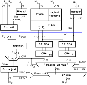
Figure 6: TFP multiplier (RTN variant).
| RTN | RTNE | difference |
|---|
| max. delay [ps] | 944 | 945 |
| |
| AREA |
| combinational | 11,540 | 13,760 | +20% |
| registers | 1,320 | 1,320 | - |
| Total | 12,860 | 15,080 | +17% |
| |
| Total power [mW] | 18.98 | 21.57 | +14% |
|
Table 4: Post synthesis comparison between RTN and RTNE TFP-mult.
The delay of the critical is identical and both units meet the timing constraint
of TC=1.0 ns. The area in the functional blocks of RTNE is about 20%
larger than in the RTN unit.
This overhead is reduced to about +17% when
the input and pipeline registers are accounted for.
The power dissipation is measured at frequency 1 GHz for binary32
operands (worst case). The power overhead for the RTNE unit is about 14%.
The TFP multiplier is intended to be used in accelerators as an element of a
multi-lane vector unit. Although the overheads are not very large, for a given
area or power footprint we can fit more RTN units. For example, if the
power budget is 150 mW we can fit 8 RTN-mults vs. 7 RTNE-mults.
Moreover, the error analysis done for the case of matrix multiplication,
reported in Figure 7, suggests that the difference
between the RTN and RTNE rounding modes is not critical.
For these reasons, we selected the RTN unit of Figure 6 for
the evaluation of the power efficiency by TFP.
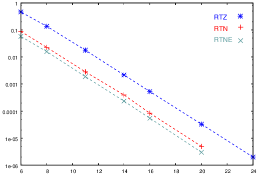
Figure 7: Average error for 50×50 matrix multiplication under TFP rounding modes.
4.1 TFP Multiplier Experiments
To have a more accurate evaluation, we built the layout for a single
TFP RTN-mult of Figure 6.
The post-layout timing and area resulted to be better than the estimates
of Table 4:
the delay of the critical path changed to 943 ps (almost identical),
but the total area is
reduced to 10,930 NAND2 equivalent gates, about 15% less than the
post-synthesis estimate.
This reduction has a positive effect on the power dissipation as explained next.
For the power dissipation, we created traces for the execution of two
algorithms: matrix multiplication and Gaussian elimination.
We sampled several m and e values for the two algorithms, and
we run post-layout simulations (Synopsys VCS) for several test cases.
By comparing power figures for the same m, but different exponent
bit-width e, we noticed a small difference. The reason is that most of
the power in a FP multiplier is dissipated in the significand computation.
For example by comparing e=8 and e=5 for m=11, the difference in
power dissipation in the exponent path is less than 30%. However, the
exponent path impacts less than 3% the total power of the TFP-mult with m=11.
Therefore, from a power dissipation point of view, going from e=8 to
e=5 results in a overall power reduction of less than 1%.
Since the power savings in reducing the exponent bit-width are not significant,
and to simplify the presentation of the experimental results, we opted for
test patterns with fixed exponent e=8.
For the two algorithms, we run post-layout power
estimation for the following significand bit-widths:
- Matrix multiplication, square 50×50 matrices:
m={ 24, 20, 16, 14, 11, 8, 6}.
- Gaussian elimination, systems of order 5:
m={ 24, 20, 16, 14, 11, 9}.
The results for the total average power dissipation are reported in
Table 5 and plotted (together with the trends) in
Figure 8.
| | Matrix multiplication | Gauss elimination |
|---|
| m | Pave [mW] | ratio | Pave [mW] | ratio |
|---|
|
24 | 10.83 | 1.00 | 12.67 | 1.00 |
| 20 | 10.77 | 0.99 | 11.58 | 0.91 |
| 16 | 10.70 | 0.99 | 9.79 | 0.77 |
| 14 | 10.11 | 0.93 | 9.23 | 0.73 |
| 11 | 8.50 | 0.78 | 7.87 | 0.62 |
| 9 | | | 6.47 | 0.51 |
| 8 | 6.10 | 0.56 |
| 6 | 5.11 | 0.47 |
|
|
| Pave measured at 1 GHz.
|
|
Table 5: Average power dissipation for TFP-mult (RTN) as m scales (e=8).
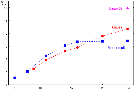
Figure 8: Trends of average power dissipation for TFP-mult (RTN) as m scales (e=8).
5 Conclusions and Future Work
In this report, we presented a Tunable Floating-Point representation to reduce
precision and dynamic range of floating-point numbers when the rounding
error produces still acceptable results. The main purpose of TFP is to reduce
the energy footprint of accelerators by introducing flexibility in the
choice of significand and exponent bit-widths.
The main contribution is the design of a TFP multiplier providing correct
rounding for the selected precision, and reduced power dissipation.
The TFP-mult can be deployed in an array to form a multi-lane multiplier.
In presenting the results of two simple algorithms implemented, we opted
for a simple round-to-the-nearest (RTN) unit. However, in future work, we plan
to implement a TFP-mult supporting IEEE 754' roundTiesToEven (RTNE)
and make programmable the rounding mode by disabling the blocks not used
in a specific mode. In this way, we can increase the flexibility of the accelerator
and keep a good power efficiency.
We also plan to extend TFP to the other operations: addition, division and square root.
References
- [1]
-
IEEE Standard for Floating-Point Arithmetic, IEEE Computer Society
Std. 754, 2008.
- [2]
-
M. Ercegovac and T. Lang, Digital Arithmetic. Morgan Kaufmann Publishers, 2004.
- [3]
-
E. M. Schwarz, R. M. A. III, and L. J. Sigal, "A radix-8 CMOS S/390
multiplier," in Proc. 13th IEEE Symposium on Computer Arithmetic
(ARITH), July 1997, pp. 2-9.
- [4]
-
N. Burgess and C. N. Hinds, "Design of the ARM VFP11 Divide and Square Root
Synthesisable Macrocell," Proc. of 18th IEEE Symposium on Computer
Arithmetic, pp. 87-96, July 2007.
Footnotes:
1The dynamic range is the ratio between
the largest and the smallest (non-zero and positive) number [2].
2ulp is the unit in the last position.
3
CSA: carry-save adder. CPA: carry-propagate adder.
4A 1 FO4 delay is the delay of an inverter of minimum
size with a load of four minimum sized inverters.
File translated from
TEX
by
TTH,
version 4.06.
On 15 Mar 2018, 15:14.