|
Copyright 2001 IEEE. Published in the Proceedings of 2001 IEEE International Symposium on Circuits and Systems (ISCAS), Vol. II, pages 305-308, Sidney, Australia, May 6-9, 2001.
The new generation of telecommunication equipment often require the use of high order high-speed low-power Finite Impulse Response (FIR) filters which can be effectively implemented by using the Residue Number System (RNS) arithmetic.
The use of the RNS allows the decomposition of a given dynamic range in slices of smaller range on which the computation can be efficiently implemented in parallel [1], [2]. The drawback presented by the RNS is the overhead introduced by the input and output conversions from binary to RNS and vice versa. This overhead (latency and area) can be reduced by using efficient conversion techniques [3], [4].
Recently, the RNS has gained importance in low power design. In [5] and [6] the power dissipation is reduced by taking advantage of the speed-up due to the parallelism of the RNS structure.
In this work, we explore the design work-space of FIR filters with respect to their structure (direct or transposed form), characteristics (constant or variable coefficients), and number of taps. We compare their implementations in the traditional Two's Complement System (TCS) with RNS implementations and consider speed, area and power dissipation tradeoffs. We emphasize on power dissipation aspects for which RNS seems to be better (lower consumption) than TCS.
The filters have been implemented in a 0.35 mm library of Standard Cells. Delay, area and power dissipation have been determined with Synopsys tools.
Results show that, for a relatively large number or taps, RNS filters offer smaller area and power consumption than corresponding TCS filters.
A FIR filter could be realized in either direct or transposed form (Figure 1). As a starting point in our design, we chose input and coefficients size of 10 bits and assumed that a 20-bit dynamic range is enough to have an error-free filter. However, we also extended our investigation to two's complement truncated FIR filters.
A key point in the design of the RNS filter is the choice of moduli.
In order to cover the dynamic range of 20 bits, we chose a set of prime
numbers, which simplify the multiplications, as explained later, and
a power of two (modular operations are trivial) to boost the range.
Based on results of simulations, we chose for our RNS filters the following
set of moduli
|
 |
Because FIR filters in transposed form are modular with respect to the number of taps (i.e. adding extra taps does not alter the filter architecture), we set as the main design constraint the maximum delay (i.e. the critical path) which is the propagation delay between two registers in adjacent taps (see Figure 1.a).
The composing blocks of a FIR filter are multipliers, adders and registers. In the following, we describe the architectures chosen for implementing these composing blocks.
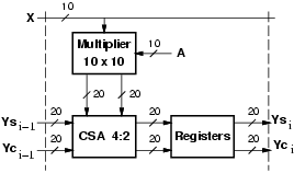
For the implementation of multipliers with the traditional binary system (TCS), we chose to keep the product in carry-save (CS) format in order to speed-up the operation, and delayed the assimilation of the CS representation to the last stage of the filter. For the FIR filter in transposed form (Figure 1.a), in each tap we need to add the CS representation of the product to the value stored in the register (previous tap). Again, to avoid the propagation of the carry, we can store the CS representation. For this reason, we need to implement the addition with an array of 4:2 carry-save adders (CSA), as shown in Figure 2.
 |
The CS representation is finally converted into the two's complement representation by a carry-propagate adder (realized with a carry-look-ahead scheme) in the last stage of the filter.
Figure 2 shows the implementation of the tap of a filter with programmable coefficients. For filters with constant coefficients (not programmable) the implementation scheme is the same with the only difference in the multiplier which is simplified.
For both, variable and constant coefficients, implementations the critical
path is:
|
|
|
The results are summarized in Table 1 with their actual values.
| ||||||||||||||||||||||||||||||||||||||||||||||||||||||||||||||||||||||||
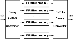
As already mentioned, a RNS filter can be decomposed, as shown in Figure 3, into P filters of smaller dynamic range (P is the number of moduli) working in parallel.
 |
In each tap, a modular multiplier is needed and because of the complexity of modular multiplication, we used the isomorphism technique to implement the product of residues for prime moduli (except 3) [7]. By using isomorphisms, the product of the two residues is transformed into the sum of their indices which are obtained by an isomorphic transformation (see [8] for implementation detail).
In case of filters with constant coefficients, the multiplication for a constant can be easily performed by a look-up table implemented with synthesized logic.
The addition is also a modular operation and a correction step is needed if the result of the binary addition exceeds the modulo (see [8] for implementation detail).
As already mentioned, the RNS FIR filter is completed by an input and an output conversion block.
The critical path for RNS filters in transposed form is:
|
| variable coeff. | constant coeff. | |||||
| mod | Delay | Area | Power | Delay | Area | Power |
| [ns] | [mW] | [ns] | [mW] | |||
| 3 | 1.7 | 37 | 0.25 | 1.1 | 24 | 0.14 |
| 5 | 3.4 | 77 | 0.62 | 2.8 | 65 | 0.41 |
| 7 | 3.8 | 93 | 0.84 | 1.9 | 50 | 0.41 |
| 11 | 5.0 | 175 | 1.75 | 3.2 | 98 | 0.96 |
| 17 | 5.0 | 175 | 1.76 | 4.3 | 148 | 1.24 |
| 64 | 3.2 | 188 | 1.66 | 2.5 | 116 | 0.98 |
| Area as number of NAND2. | ||||||
| Power at 100MHz assuming random input activity. | ||||||
Sometimes accuracy is traded with performance by implementing filters with truncated dynamic range. Truncation or rounding schemes are very tricky to be implemented in RNS, and for this reason we limited our investigation to TCS filters. We have tried different truncation schemes, but we report here only the case in which the results of multiplications are truncated after 10 bits. Table 1 shows the values for the truncated implementation of the filters with variable and constant coefficients.
The table shows that the RNS filter has a higher latency, due to the conversions, but it can be clocked at the same rate of the TCS filters and sustain the same throughput. Moreover for error-free filters (first two rows) the RNS filter is better than the corresponding TCS for more than 8 taps. Even if we compare the truncated TCS filters with error-free RNS filters, the RNS filters show smaller area and power dissipation when the number of taps is larger than 40.
Furthermore, in RNS filters by lowering the supply voltage for moduli not in the critical path (moduli 3, 5, 7, and 64, according to Table 2) the power dissipation can be further reduced without affecting the overall performance [8].
| ||||||||||||||||||||||||||||||||||||||||||||||||||||||||
For the FIR filter in direct form (Figure 1.b), it is convenient to implement the addition with a Wallace's tree to speed-up the operations. However, the use of the tree makes the design of the filter not modular in the number of taps and the delay of the structure changes with its size.
By opting for the CS representation of the products,
for a N-tap filter we have to add 2 ×N addends.
The resulting expressions for the critical path is
|
|
|
The results are summarized in Table 3 with their actual values.
In RNS direct FIR filters
a N-input Wallace's tree, followed by a block to compute
the modulo (described in [4]), is needed.
The expressions for critical path and area are the following:
|
|
Table 3 summarizes the results for the different implementations. The critical path depends on the number of levels in the tree (and consequently, on the number of taps). We can introduce pipeline latches to speed-up operations, but we increase area and power. For the error-free with variable coefficients filters (first row in Table 3) the critical path is almost the same, but the RNS is smaller and consumes less power for N > 8. For the error-free with constant coefficients filters (second row), the RNS is faster (about 1.7 ns less), and its area start to be smaller for more than 16-tap filters.
The results presented here, show that for high-order FIR filters the RNS implementations gives the same throughput as filters implemented in the traditional two's complement system (TCS), but have smaller area and power consumption. Even truncated TCS FIR filters are not performing better than error-free RNS for filters with a large number of taps. Moreover, our investigation showed that FIR in transposed form gives a better performance at expenses of a larger area and power dissipation.