|
Copyright 2000 IEEE. Published in the Proceedings of 43rd IEEE Midwest Symposium on Circuits and Systems, Volume 1, pages 320-323, Lansing (MI), USA, Aug. 8-11, 2000.
The new generation of telecommunication equipment often require the use of high order FIR filters for the implementation of the new modulation schemes. Moreover, the telecommunication market demands for speed and low power consumption for the new portable multimedia terminals. In this context, computational intensive signal processing blocks can be effectively implemented by using Residue Number System (RNS) arithmetic.
The use of the RNS allows the decomposition of a given dynamic range in slices of smaller range on which the computation can be efficiently implemented in parallel [1], [2], [3]. The typical drawback presented by the RNS is related to the input-output conversion from binary to RNS and vice versa. This problem is solved by using new efficient conversion techniques [4], [5] or by converting directly the analog signal in the residue representation and vice versa [6]. Recently, a number of works on low power and RNS have been presented. In [7] and [8] the power dissipation is reduced by taking advantage of the speed-up due to the parallelism of the RNS structure. The supply voltage is reduced, resulting in a quadratic reduction of power, until the speed-up = 1 [7] or until the desired value of delay [8]. In [9] some encoding optimization techniques for small moduli (3 and 7) are presented.
In our work, we compare the performance, area and power of a FIR filter realized with the traditional binary arithmetic, with a RNS based one. Although the RNS filter has the same performance of the traditional one, its area and power dissipation are smaller for filters with more than eight taps. Furthermore, we reduce power dissipation, without sacrificing performance, by equalizing the parallel paths of the RNS filter with a dual voltage approach [10].
The starting point of our design is a programmable N taps FIR
filter
|
To have an error-free filter we must keep a number of bits sufficient to hold the carry-save representation of the sum at the k-th tap. In the worst case, we need to store 2 ·(10 ·10 + log2 N) bits per tap. The CS representation is finally converted into two's complement representation by a carry-propagate adder (realized with a carry-look-ahead scheme) in the last stage of the filter.
 |
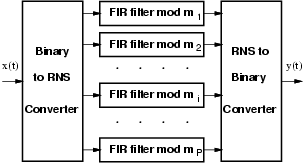
The RNS implementation of the FIR filter is shown in Figure 3. The FIR filter is decomposed into P filters working in parallel, where P is the number of moduli used in the RNS representation. In addition, the RNS filter requires both binary to RNS and RNS to binary converters.
 |
In order to have a dynamic range of 20 bits, as in the
case of the traditional implementation, we chose the following set of
moduli:
|
|
In each tap, a modular multiplier is needed to compute the term áak x(n-k)ñmi. Because of the complexity of modular multiplication, we used the isomorphism technique [13] to implement the product of residues in all the moduli but 3 (multiplication can be easily computed in tabular way) and 64 (modular product corresponds to the 6 least-significant bits of the conventional product). By using isomorphism, the product of the two residues is transformed into the sum of their indices which are obtained by an isomorphic transformation. According to [13], if m is prime there exists a primitive radix q such that its powers modulo m cover the set [1, m-1]:
|
|
|
For example, for the modular multiplication
|
|
 |
Because of the transposed form of the FIR filter, the input x is the multiplicand of all the multiplications (see Figure 1). For this reason only one isomorphic transformation, incorporated in the binary to RNS conversion, is necessary for all the taps. On the other hand, because the coefficients of the filter (multiplicators) are constant terms loaded once at start-up, it is convenient to load directly the isomorphic representation modulo mi-1. As a result, in each tap, we reduce the modular multiplication to a modular addition followed by an access to table (inverse isomorphism) as depicted in Figure 4. The table is implemented as synthesized logic and special attention has to be paid when one of the two operands is zero. In this case there exists no isomorphic correspondence and the modular adder has to be bypassed.
 |
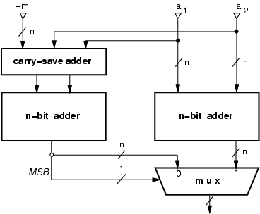
The modular addition
áa1 + a2 ñm,
consists of two binary additions. If the result
of a1 + a2 exceeds the modulo (it is larger than m-1),
we have to subtract the modulo m. In order to speed-up the operation
we can execute in parallel the two operations:
|
As already mentioned, the input conversion block includes the isomorphic transformation. If x is zero, there is no exponent w such that áqw ñmi = 0. As a consequence, zero is encoded with a special pattern that is then detected in the block which computes the product using the isomorphism.
The output conversion is implemented by using the Chinese Remainder Theorem, as described in [4].
Both the traditional and the RNS filters were implemented in a 0.35 mm library of Standard Cells. Delay, area and power dissipation have been determined with Synopsys tools.
Table I summarizes the results. In the table, area is reported as number of NAND2 equivalent gates and power is computed at 100 MHz. However, both area and power dissipation do not take into account the contribution of interconnections.
Filter Cycle Latency Area Power [ns] (cycles) (gate equiv.) [mW] Trad. 5.0 N+1 230+1250N 14.9 + 13.5N RNS 5.0 N+3 2910+745N 51.0 + 6.9N
 |
Table I shows that the RNS filter has a higher latency, due to the conversions, but it can be clocked at the same rate of the traditional filter, and consequently, it can sustain the same throughput. The table also shows that the conversion overhead of the RNS filter is soon offset by the smaller area/power per tap, as the number of the taps increases.
More details on the implementation of the different paths corresponding to the moduli mi for the RNS filter are presented in Table II.
Modulus Delay Area Power [ns] (gate equiv.) [mW] 3 1.7 37 0.25 5 3.4 77 0.62 7 3.8 93 0.84 11 5.0 175 1.75 17 5.0 175 1.76 64 3.2 188 1.66
Because the single tap delay of moduli 3, 5 and 64 is less than
3.5 ns, and in order to obtain a larger reduction in power
dissipation, we can use the available time slack
(5.0-3.5 = 1.5 ns) to lower the supply voltage for these
moduli. For this specific case, a time slack of 1.5 ns, which
corresponds to 30% of the cycle time, allows a reduction of the
supply voltage from 3.3 V to 2.7 V without affecting the
overall performance.
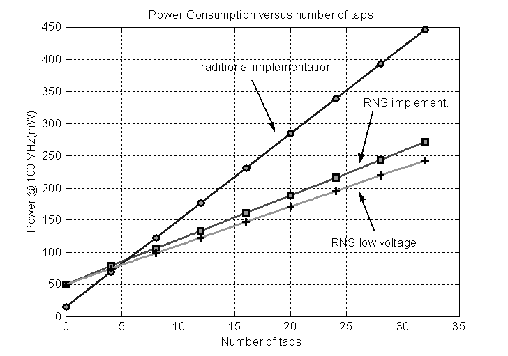
We estimated the new power expression of the RNS filter to be
| (1) |
The expressions for area and power of Table I and Expr. (1) are plotted in Figure 6 and Figure 7. From the figures it is clear that for a filter with a number of taps larger than eight the RNS implementation of the filter outperforms the traditional one.


We have implemented a RNS FIR filter and compared its delay, area and power with those of a traditional FIR filter in transposed form. The results obtained show that the RNS filter can sustain the same clock rate, although it has a slightly longer latency. However, in terms of area and power the RNS version is more convenient for filters with more than eight taps. An additional reduction of about 15% is possible by using dual voltage.
*This work was partially supported by MURST National Project: Codesign Methods for Low Power Integrated Circuits.