Figure 1: Implementation of radix-r division
| If you are unable to display correctly math fonts in Netscape under X11, click here. |
Alberto Nannarelli and Tomas Lang
Department of Electrical & Computer Engineering
University of California, Irvine, California 92697
e-mail : alberto@ece.uci.edu, tomas@ece.uci.edu
A reduction of about 40% in the energy consumption is obtained for both radices (about 70% if low-voltage gates, for dual voltage implementation, are available). Also the results show that the radix-8 divider is about 20% faster and the energy dissipated to perform a division is about the same, with respect to the radix-4.
Tradeoffs between area and delay have always been something designers of ICs had to deal with. Recently, with the advent of portable electronics and the increased density on chip, also power dissipation started to play an important role in the design process and power consumption constraints cannot be neglected any longer. Our work is focused on the evaluation of different schemes in the design of low-power floating-point dividers and their power-delay tradeoffs. The division algorithm implemented is the modified SRT for radices greater than 2 [1]. It is known that the use of higher radices in division, reduces the number of cycles required to complete the operation, but increases the complexity of the circuit. In this paper we study the influence of the radix on the power dissipation. More specifically, we compare the performance and the energy consumption per operation for a radix-4 and a radix-8 divider. In a radix-4 divider 2 bits of the quotient are retired in each iteration, whereas in a radix-8 the number of bits retired is 3. Consequently the radix-8 divider has the advantage of requiring fewer iteration to compute the mantissa of the quotient at the expense of a longer iteration cycle (slower clock) and larger area.
A number of well-known techniques for the reduction of power ([2] and [3]) are used along with some techniques specific to the division algorithm [4]. We first explain how those techniques are applied to the divider independently of the radix and then we detail the different choices and the necessary adjustment to the radix-4 and radix-8 cases.
The low-power implementation of the radix-4 divider is directly derived from that presented in [5]. With respect to the techniques presented there we have added the following:
considered the use of dual voltage, and
partitioned and disabled the quotient-digit selection function.
The units are implemented using the Passport 0.6 mm CMOS standard cell library [6]. This library does not provide low-drive (or low-power) cells for all the logic gates, and this limits the design choices. Furthermore, because of the use of automatic floorplanning, we loose the control on the placement of cells, and this reflects on variations in the interconnection capacitance, among different layouts, that sometimes hide the benefits of the technique applied (e.g path equalization). The power estimation has been carried out with PET [7], a power evaluation tool which computes the power dissipated in a circuit from the netlist extracted from the layout, the standard cell library characteristics, and the results of a logic-level simulation.
Results show that is possible to get a reduction of about 40% in the energy-per-division for both the radices (about 70% if low-voltage gates, for dual voltage implementation, are available). Also the radix-8 divider is about 20% faster and the energy dissipated to perform a division is slightly larger, with respect to the radix-4.
The division algorithm, described in detail in [1], is implemented by the residual recurrence
|
| (1) |
The quotient digit is in signed-digit representation {-a, �,-1,0,1, �, a} and is determined, at each iteration, by the selection function
|
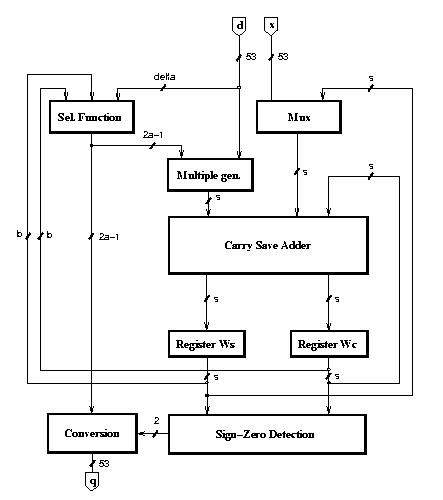
The implementation is shown in Figure 1. The recurrence is implemented with the selection function, the multiple generator, the carry-save adder (CSA) and two registers to store the carry-save representation of the residual. The conversion block performs the conversion and the rounding according to the sign of the final residual and the signal that detects if it is zero, which are produced by the sign-zero-detection block (SZD). The scheme is completed by a controller (not depicted in the figure).
Figure 1: Implementation of radix-r division
The radix-4 divider requires 30 iterations (clock cycles) to produce the quotient: 28 cycles to produce the necessary quotient digits plus additional cycles for the initialization of the operands and the final rounding. Similarly, the number of iterations required for the radix-8 divider is 20.
The performance metric is the time elapsed per operation which is
tdiv = Tcycle ×(no. of iterations)
In order to have a measure of the power dissipated independent by the frequency, we measure the energy-per-division, that is
|
|
In this section we describe the design techniques and the modifications of the algorithm to obtain a reduction in the power dissipation (i.e. in the energy-per-division). The modifications are done with the constraint of not deteriorating the timing of the circuit. Some of the techniques illustrated below have already been presented in [5] (techniques in Sec. 3.1-3.3). In addition, Section 3.4 describes the use of dual voltage, which is more effective than the use of lower-drive cells, Section 3.5 the partitioning of the selection function, and Section 3.6 describes the modification in the conversion algorithm and its low-power implementation. With respect to [5], the path-equalization technique has been abandoned because, due to the automatic floorplanning of the layout, we could not control the interconnection delay and the improvement obtained was very small.
The modification consists in switching-off blocks which are not active during several cycles. This is the case for the sign-zero-detection block (SZD), which is only used in the rounding step. The SZD can be switched off by forcing a constant logic value at its inputs during the recurrence steps.
The position of the registers in a sequential system affects the power dissipation. Retiming is the circuit transformation that consists in re-positioning the registers in a sequential circuit without modifying its external behavior [8]. By retiming the recurrence we reduce the number of spurious transitions, reduce the switching activity in some blocks, and change the critical path. The retiming is done by moving the selection function of Figure 1 from the first part of the cycle to the last part of the previous cycle (see Figure 2). We have to introduce a new register to store the quotient digit, but the register qj is quite small, a few bits, and it does not compromise the energy saving obtained by retiming. Now the critical path is limited to a few most-significant bits in the recurrence and the rest of the bits can be redesigned for low power.

Figure 2: Radix-r retiming
Since the contribution of flip-flops to both power dissipation and area is significant, it is convenient to change the redundant representation of the residual (wS and wC) to reduce the number of flip-flops in the registers. By using a radix-r carry-save representation with log2r sum bits and one carry bit for each digit, we only need to store one carry bit for each digit, instead of log2 r. Furthermore, after the retiming, the b MSBs, assimilated in the adder inside the selection function block (Figure 2), can be stored in wS eliminating b flip-flops in wC (see Figure 6 and 8).
The change in the redundant representation requires a redesign of the carry-save adder to propagate the carry inside the digit. The propagation of the carry increases the delay so that this modification cannot be made for those cells (digits of w) that are in the critical path. However, these cells are few after the retiming.
The power dissipated in a cell depends on the square of the voltage supply (VDD) and a significant amount of energy can be saved by scaling VDD [9]. However, by lowering the voltage the delay increases, so that to maintain the performance this technique is applied only to cells not in the critical path. Different power supply voltages require level-shifting circuitry that dissipate a not negligible amount of power. As a consequence, it is convenient to apply this technique only if the number of cells not in the critical path is quite large, and the power increase in the level-shifting circuitry does not offset the reduction due to voltage scaling. However, by using two voltages we only need to level-shift when going from the lower to the higher voltage [10]. In the case of the divider, as shown in Figure 3, the s-b least-significant bits, can be redesigned for low-voltage. The voltage-level shifters are not needed until a specific digit moves towards the b-MSBs, by shifting across iterations, and into the critical path. By placing the voltage-level shifters in the digit immediately before the b-MSBs the cycle time is not increased.
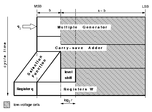
Figure 3: Dual voltage
It was not possible for us to implement dual voltage because our library does not provide low-voltage cells. We roughly estimate that the use of low-voltage cells in the s-b LSBs of the recurrence produces a power reduction of about 50% in the recurrence. This value is calculated allowing the s-b LSBs to be twice as slow as the b MSBs, and that results in a possible power supply scaling from VDD to VDD/2 with a quadratic decrease of the power dissipated. Only log2 r level-shifters (low to high) are needed (Figure 3) in the recurrence.
In the parts of the circuit where many level-shifters are required, for example the selection function, low-drive cells are used instead of low-voltage gates.
The quotient-digit selection is a function of some bits of the divisor and of the residual. Since the divisor is fixed for the whole division operation, from the point of view of energy consumption it is convenient to decompose the function into subfunctions and to enable only the subfunction corresponding to the actual value of the divisor. This is specially convenient for higher radices, because the quotient-digit selection is more complex and therefore is responsible for a significant portion of the energy.
The on-the-fly convert-and-round algorithm [1] performs the conversion from the signed-digit representation to the conventional representation in 2's complement. The conversion is done as the digits are produced and does not require a carry-propagate adder. The algorithm, in its original formulation, did not take into account power dissipation constraints and, as a result, quite a big amount of energy is dissipated in the unit. In this paper we don't describe the details of the algorithm and its low-power modification, refer to [4] for the complete description, but we just sketch the sources of the power consumption and the remedies adopted.
The partial quotient is stored in two or three registers, depending on the redundancy factor a/(r-1). These registers are updated in each iteration and the final quotient is chosen among those registers during the rounding. The update of the registers is done by shift-and-load operations.
The large amount of power dissipated in the unit is mainly due to the shifting during each iteration and to the number of flip-flops, used to implement the registers, especially in the 3-register implementation.
As a first step to reduce power dissipation, we load each digit in its final position. In this way we avoid to shift digits along the registers. To determine the load position we use a m-bit ring counter C, one bit for each digit to load.
As a second step, we reduce the partial-quotient registers from two (or three) to one, as follows:
When the redundancy factor a/(r-1) = 1, the original algorithm requires also a third register QP to be used in the rounding step when it is necessary to add 1 to a digit that is already r-1 (max. value representable in log2 r bits) and propagate the carry. In the modified algorithm, the register QP is eliminated by recoding the quotient digit into the digit set { -(r-1), �, -1, 0, 1, �, r-2}. This requires to store the current quotient digit in a temporary register T (log2 r bits + 1 sign bit).
With the implementation of the modified algorithm we reduce the number of flip-flops in the convert-and-round unit from 2n (or 3n) to n+[n/(log2r)].
Summarizing, the algorithm is modified by eliminating the shifting of the digits previously loaded and one or two partial quotient registers. An additional register, the ring counter, is introduced to keep track of the digits to update.
As a further step to reduce the power dissipation in the convert-and-round unit, we switch off the clock signal for the flip-flops that don't have to be updated. Figure 4 shows an application of the gated flip-flop technique [11]. We introduce the activation function F, that enables the clock of the flip-flop only when it is needed. The activation function F must be ANDed with the clock signal clk for trailing-edge-triggered flip-flops. For leading-edge-triggered (rising edge) flip-flops an AND gate cannot be used, to avoid a malfunctioning of the circuit if the delay d of F is shorter than the high period of the clock h, as shown in Figure 4.a (d < h). By ORing the inverted F with the clock we obtain the desired result cp for leading-edge-triggered flip-flops (Figure 4.b). Note that the problem is still present if d is larger than h, but in the case of the converter d is short compared to the critical path of the divider and the clock period T must be larger than the critical path for a correct operation.

Figure 4: Gated flip-flop enabling function
The modified conversion algorithm requires that the converted digit be presented to the full array of flip-flops, and then, only log2r of them are loaded with this digit. To distribute the digit and the clock we need a tree (Figure 5.a) that dissipates a significant amount of power. By dividing the register Q into two portions, upper (n/2 most-significant bits) and lower (n/2 least-significant bits), we can switch-off a part of the tree for the first half iterations. Figure 5.b shows how this is obtained by dividing the tree into two halves and by propagating the signal to the upper array of flip-flops when executing the first half of the iterations and to the lower array in the rest. Signals AU and AL = [`AU] select the half array to feed. By implementing this gated-tree we can save an ideal 50% in the power dissipated to distribute the signals. However, the actual reduction is less than 50% because the gates introduce extra capacitance, and also the transitions are not equally distributed in the two portions of the array.

Figure 5: Gated Tree. a) before, b) 50% reduction
The low-power implementation of a radix-4 divider is directly derived from that presented in [5]. With respect to that implementation we added here a low-power convert-and-round unit as described is Section 3.6. Furthermore the circuit was re-laid-out with a new library (same feature size of 0.6 mm, but 3 metal layers) and the results are slightly different.
The energy-per-division in the standard implementation, optimized for minimum latency, is 45.4 nJ. The critical path is 8.3 ns, allowing a clock frequency of 120 MHz.
The low-power implementation of the radix-4 divider is shown in Figure 6. The energy-per-division dissipated in the convert-and-round unit is reduced from 12 nJ to 3.7 nJ, and the overall energy-per-division is 27 nJ, while the area is 1.2 mm2.

Figure 6: Low-power implementation of radix-4 divider
An estimation of the energy-per-division of a possible implementation with dual-voltage is 14.3 nJ. The power reduction with respect to the basic divider is about 70%.
For the radix-8 divider the quotient digit set is {-7, �,-1,0,1, �,7}. In this case, to avoid the implementation of a complicated multiple generator, the quotient digit is split into two parts qH with weight 4 and qL with weight 1 (see [1]) and the digit set of each part is reduced to {-2,-1,0,1,2}. Since the redundancy factor is a/(r-1) = 1, in this case, we need three registers (Q, QM, and QP) in the convert-and-round unit.
The standard implementation, shown in Figure 7, has a critical path of 10.7 ns corresponding to a maximum clock frequency of 93 MHz, and its energy-per-division is 47.7 nJ.
By retiming the recurrence, changing to radix-8 the LSBs in the carry-save adder, and by disabling the SZD unit during the recurrence steps, we obtain the implementation shown in Figure 8. By implementing the modified convert-and-round algorithm, we reduce the number of flip-flops from 171 (registers Q, QM, QP) to 81 (registers Q, C, T).
Table 1 shows the energy-per-division dissipated in the blocks. Entry ßtd" refers to the standard implementation, optimized for speed, entry "l-p" is the low-power implementation, and "d-v" is the estimate of a possible dual-voltage implementation. Values marked * include level shifters.
| blocks | std | l-p | d-v |
| control | 0.6 | 0.6 | 0.6 |
| clk tree | 0.4 | 0.4 | 0.4 |
|
mux | 1.4 | 0.2 | 0.1 |
| mul. gen. H | 3.1 | 1.8 | 0.7 |
| CSA H | 4.4 | 4.2 | 1.5 |
| mul. gen. L | 2.6 | 1.7 | 0.6 |
| CSA L | 6.0 | 5.3 | 1.9 |
| sel. func. | 3.6 | 4.0 | 4.0 |
| register wc | 4.2 | 1.2 | 0.4 |
| register ws | 4.2 | 4.0 | *1.4 |
| register qL | - | 0.2 | 0.2 |
| register qH | - | 0.2 | 0.2 |
| total recur. | 30.5 | 23.8 | 12.0 |
|
SZD | 3.8 | 1.0 | 1.0 |
| C&R unit | 13.4 | 2.8 | *1.0 |
| total C&R | 17.2 | 3.8 | 2.0 |
|
Total divider | 47.7 | 27.6 | 14.0 |
| Ratio | 1.00 | 0.59 | 0.30 |
|
Area mm2 | 2.2 | 1.8 | - |
The energy-per-division in the low-power implementation of the radix-8 divider is 27.6 nJ, and the area of the unit is 1.8 mm2.
We estimated that by implementing the unit with dual-voltage the energy-per-division becomes 14.0 nJ, corresponding to a reduction of 70%.
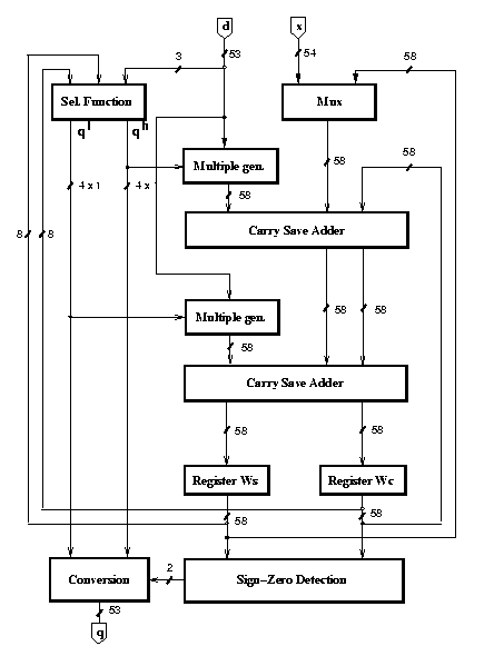
Figure 7: Standard implementation of radix-8 division

Figure 8: Low-power implementation of radix-8 divider
Table 2 summarizes the characteristics of the two dividers. The energy-per-division is split in the contribution of the recurrence and that of the conversion and rounding.
| radix-4 | radix-8 | |||||
| std | l-p | d-v | std | l-p | d-v | |
| Ediv rec. [ nJ ] | 27.7 | 21.6 | 11.4 | 30.5 | 23.8 | 12.0 |
| Ediv conv. [ nJ ] | 17.7 | 5.4 | 2.9 | 17.2 | 3.8 | 2.0 |
|
Ediv total [ nJ ] | 45.4 | 27.0 | 14.3 | 47.7 | 27.6 | 14.0 |
|
Ratio | 1.00 | 0.59 | 0.31 | 1.00 | 0.59 | 0.30 |
|
Tcycle [ ns ] | 8.3 | 8.3 | 8.3 | 10.7 | 10.7 | 10.7 |
| tdiv [ ns ] | 250 | 250 | 250 | 214 | 214 | 214 |
| Area [ mm2 ] | 1.4 | 1.2 | - | 2.2 | 1.8 | - |
The table shows, for both the radix-4 and the radix-8 dividers, a reduction in the energy-per-division of about 40% in the low-power implementation. An implementation with dual voltage will show a reduction of about 70% for both radices. The speed-up for the radix-8 over the radix-4 is about 17%, while the increase in the energy-per-division is less than 2% in the low-power implementation. In the dual voltage implementation, our estimate indicates that the energy-per-division in the radix-8 is even smaller than in the radix-4. The radix-8 has a larger energy-per-cycle, 1.38 nJ, compared to the radix-4, 0.9 nJ. Furthermore, we notice that in the low-power implementation the area is reduced. This is due to the reduction in the number of flip-flops both in the recurrence (change of redundant representation) and in the conversion-and-round unit (elimination of registers QM and QP).
In this paper we explored the influence of the radix in the power dissipation of a floating-point divider. It was already known that by increasing the radix the operation time decreases, unless the increased cycle time offsets the benefit of a reduced number of iterations, while there is an increase in the area. On the other hand, the impact of the radix on power had not been explained. An increase in the area sometimes implies an increase in the power dissipation. Our designs show that the increase of area (about 50%) does not reflect on the energy dissipated to complete an operation, that is almost the same. The radix-4 divider is smaller, but it is slower and consumes almost the same amount of energy. It is up to the designer to decide which of the two implementation to use according to the constraints of the design.