|
This page contains brief descriptions of various techniques for
polygonizing isosurfaces, i.e. surfaces which are
a level-set of some function
f(x,y,z). To be precise, the surface is the set of points {(x,y,z) |
t=f(x,y,z)} for some value t. t is usually called the isovalue.
There are many methods for isosurface polygonization, and I do not
intend to give a survey. The goal of this page is to illustrate some
of the better known methods and demonstrate how they are connected.
I am focusing on methods appropriate for volume data and do not consider
even obvious optimizations. My main interest here is to show what kinds of meshes
that are produced.
The Original
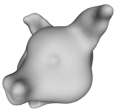
The original model is a distance field which has been volume sculpted using my
sculpting tool. A plain isosurface for t=0 is shown below.
A "cuberille" Mesh
One of the first ideas for visualizing volumes was to draw each voxel as a
small cube. If we do that we get something like the result shown below.
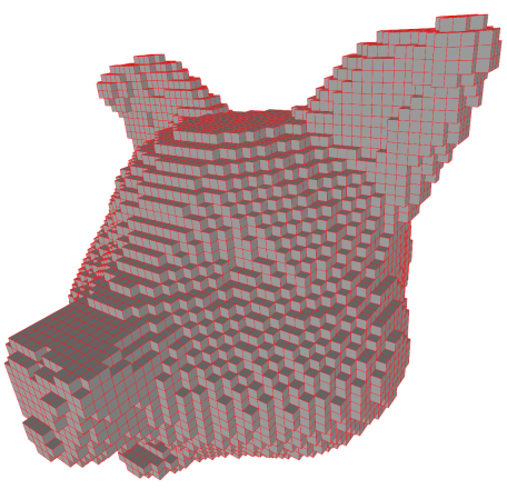
It is quite easy to get the mesh above, if we simply find every voxel with a
value greater than 0 (remember t=0) and draw a cube, but it is boring. Instead
we can select only those cube faces which separate cubes that are inside (t<0)
from cubes that are outside (t>=0).
The faces are subsequently stitched together to form a quad mesh. However,
sometimes four faces meet at an edge and in this case we must decide which
pair to stitch together. This is done using the asymptotic decider by Nielson
and Hamann. It was invented to decide ambiguous configurations in marching
cubes but it is precisely the same problem.
Dual Contouring
Who says that the vertices have to lie at the cube corners. If we place a cube
around each vertex as in the method above, we obtain a 3D grid (whose nodes
are the cube vertices) which is precisely the dual of the grid whose nodes are
the voxels (i.e. cube centers). Thus, the cuberille method is in a sense the
same as dual contouring - originally called Surface Nets by Sarah
Frisken. However, when doing dual contouring, we project the vertices onto the
surface like you see below:
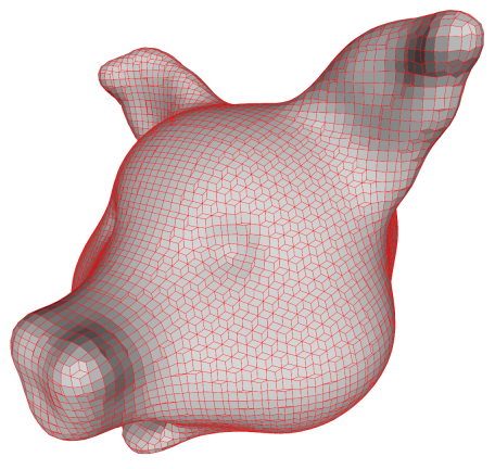
This pushing is often done by moving a vertex along the gradient direction
till it hits the isosurface. Here, a slightly improved algorithm is used which
tries to find the point on the isosurface which is closest to the original
cube corner.
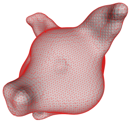
We usually need triangles, so we split the faces into triangles. Doing so
naively produces an ugly triangle mesh! Good results are obtained if we
triangulate each quad by splitting it along the shortest diagonal as shown
below.
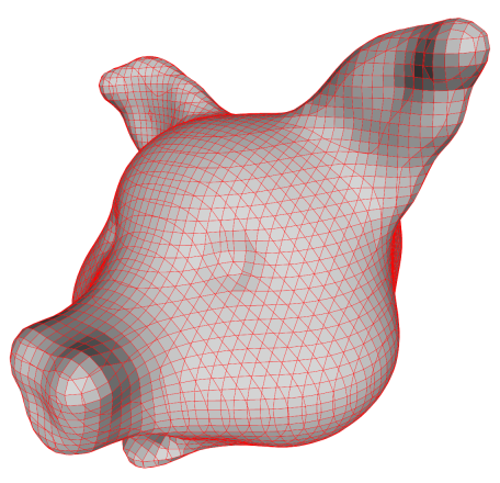
Marching Cubes
Another thing we can do is to compute the dual of the cuberille mesh. In other
words, we place a vertex in the centre of each face and connect with the
vertices on the neighbouring faces. Since all faces are quads, this produces a
mesh where every vertex is connected to four other vertices. These new
vertices don't have to be placed on the face centre. Note that the centre of
the face is precisely where the lines of the voxel grid cross the faces of the
cubes produced by the cuberille method. Thus, we can use the same method
normally used in implementations of marching cubes: We find the point on
the line segment between the two voxels sharing the cube face where the
isosurface intersects the line segment.
The result which is shown below is, in fact, the precise same result as would
have been produced by marching cubes except that the faces have not been
polygonized.
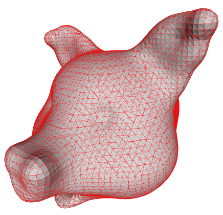
When we triangulate the faces, we get the same ugly result that we are used to
from MC. The uglyness is due to the fact that the vertex placement is more
restricted than in dual contouring.
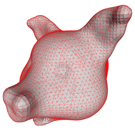
Fortunately, we can improve the mesh by collapsing very short edges as shown
below. The mesh is still ugly, but the degeneracies (edges of length zero or
almost) have been removed.
Remarks
It does seem that dual contouring produces nicer meshes than MC
but, of course, this depends on the precise method used for placing
vertices. Also a naive triangulation of the quad mesh produced by dual
contouring will produce strange results.
Marching cubes produces ugly triangles which is well known, but these
degeneracies can be fixed easily by edge collapses.
In conclusion, if triangle quality is a concern, the most important thing is
probably to use a method which produces a connected mesh and not just a set of
triangles (a triangle soup) since in this case, we can use edge collapses and
edge flips to nicify the result.
|