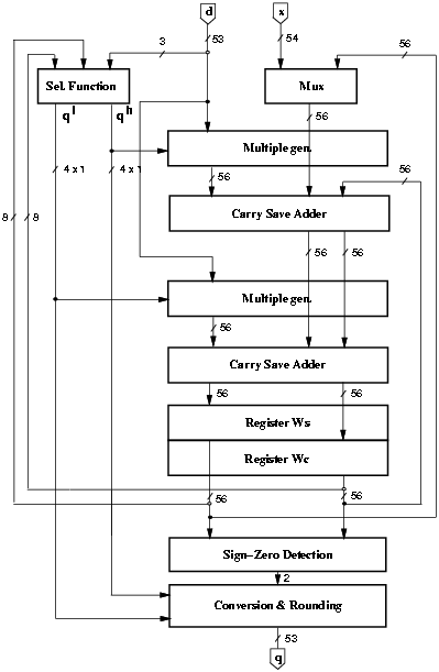
Figure 4.10: Implementation of the radix-8 divider.
The radix-8 division algorithm is implemented by the residual recurrence
|
|
In order to avoid the implementation of a complicated multiple generator, the quotient digit is split into two parts qH with weight 4 and qL with weight 1 (qj = 4qH + qL) and the digit set of each part is reduced to {-2,-1,0,1,2}.
Since the selection function (SEL) is in the critical path, to have the minimum latency we have to minimize its delay. We explored the implementation of three possible values of a: 6, 7, and 10 (the maximum value possible with the above mentioned representation). Table 4.2 shows a summary of the results. The gate-level implementation was obtained by synthesizing the VHDL description of the selection function with COMPASS ASICSynthesizer. This includes both the assimilation of the carry-save representation of [^y] and the actual digit-selection function.
| bits of | delay [ns] | ||||
| a | d | [^y] | qL | qH | gates |
| 10 | 3 | 6 | 4.0 | 3.0 | 325 |
| 7 | 3 | 8 | 3.8 | 3.0 | 370 |
| 6 | 5 | 7 | 3.8 | 2.7 | 420 |
From Table 4.2, we can see that SEL for a = 7 is as fast as for a = 6, but its area is smaller4. Surprisingly, the delay for the over-redundant case a = 10 is larger. Therefore, the SEL for a = 7 is chosen, which results in a redundancy factor r = 1. The selection logic function is described in Table 4.3.
| mh | dd | |||||||
| 8/16 | 9/16 | 10/16 | 11/16 | 12/16 | 13/16 | 14/16 | 15/16 | |
|
m7 | 27 | 30 | 34 | 36 | 40 | 44 | 48 | 48 |
| m6 | 23 | 26 | 28 | 32 | 34 | 36 | 40 | 40 |
| m5 | 18 | 20 | 24 | 24 | 28 | 28 | 32 | 32 |
| m4 | 14 | 16 | 18 | 20 | 20 | 24 | 24 | 24 |
| m3 | 10 | 12 | 12 | 12 | 16 | 16 | 16 | 16 |
| m2 | 6 | 8 | 8 | 8 | 8 | 8 | 8 | 8 |
| m1 | 0 | 0 | 0 | 0 | 0 | 0 | 0 | 0 |
| m0 | -4 | -4 | -4 | -4 | -4 | -4 | -4 | -4 |
| m-1 | -8 | -8 | -8 | -8 | -8 | -8 | -12 | -12 |
| m-2 | -12 | -12 | -12 | -16 | -16 | -16 | -16 | -20 |
| m-3 | -16 | -16 | -20 | -20 | -24 | -24 | -24 | -28 |
| m-4 | -20 | -22 | -24 | -26 | -28 | -32 | -32 | -36 |
| m-5 | -24 | -26 | -30 | -32 | -36 | -36 | -40 | -44 |
| m-6 | -28 | -31 | -34 | -38 | -40 | -44 | -48 | -52 |
| Values in table are multiplied by 16 | ||||||||
A first implementation of the divider is shown in Figure 4.10. The scheme is completed by a controller (not depicted in the figure).

Figure 4.10: Implementation of the radix-8 divider.
To have the divider compliant with IEEE standard for double-precision while operating with fractional values, 1-bit shifts are performed on the operands. Moreover, to have a bound residual in the first iteration (w[0] = x < d ), when x ³ d we shift x one bit to the right obtaining a fractional quotient. To compute the 53 bits of the quotient and an additional bit to perform rounding, 54/3 = 18 iterations are required. An additional cycle is required to load the value x as first residual w[0]. However, for the proposed architecture and selection function, the simplest way to accomplish this is to do as follows:
In conclusion, the load cycle is substituted by an extra iteration for a total of 20 iterations: 19 to compute the digits and one for the rounding. Finally, the quotient is normalized in [1,2) by shifting it four positions to the left. Note that all shifts are done by wiring and do not affect the latency of the operation. In the recurrence (w[j]) we need 54 fractional bits and 2 integer bits: one to hold the sign and the other to avoid the overflow in the CS-representation (being r = 1).
There are two possible critical paths, one going through qH and the other through qL. Since the delay of qH is smaller than that of qL, but the number of adders to traverse is larger, a good design tries to equalize the delays of both paths. The resulting critical paths are
| SEL(qL) | + mult | + HA | + reg | ||
| 4.5 | + 1.4 | + 0.6 | + 1.5 | = 8.0 ns. | |
| SEL(qH) | + mult | + HA | + FA | + reg | |
| 3.6 | + 1.4 | + 0.6 | + 0.9 | + 1.5 | = 8.0 ns. |
In conclusion, the post-layout critical path is 8.0 ns. The energy dissipated by this basic implementation is Ediv = 47.5 nJ and the contributions of the blocks is shown in Table 4.4 in column ßtandard".
For the recurrence, the retiming is done by moving the selection function of Figure 4.10 from the first part of the cycle to the last part of the previous cycle (see Figure 4.11.a and Figure 4.11.b). Two new registers (qH and qL) are needed to store the quotient digit.
However the retiming alters the critical path because the two paths through qH and qL have different delays, and now the delay of qL is added to the delay of the two CSAs (see Figure 4.11.b). To reduce the critical path to the previous value we skew the clock of register qL by the delay difference of the two paths, which, in this case, corresponds to the delay of the CSA, as shown in Figure 4.11.c. The clock can be skewed by adding the appropriate delay (e.g. some buffers) in the clock distribution tree.

Figure 4.11: Retiming and critical path.
c) after retiming and skewing the clock.
After the retiming the multiplexer is moved out of the recurrence, as shown in Figure 4.15. Consequently, the operations in the first cycle are modified by resetting registers qH and qL to 0 and -1 respectively and by storing x in w[0] = 0 - (-x).
By using a radix-8 carry-save representation as shown in Figure 4.12, we only need to store one carry bit for each digit, instead of three. This can be done for the 50 LSBs that, after the retiming, are not on the critical path. The eight MSBs, assimilated in the adder inside the selection function block (Figure 4.15), can be stored in wS eliminating another eight flip-flops in wC.
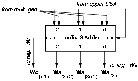
Figure 4.12: Radix-8 carry-save adder (lower).
By retiming and changing the representation, the reduction in l-p with respect to std is about 10%.
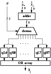
Figure 4.13: Partitioned selection function.
The quotient-digit selection is a function of three bits of the divisor and eight of the residual. In the radix-8 case, Figure 4.13 shows the partitioning in eight parts (all the possible values of d3) for both the higher and lower parts. By partitioning the selection function, we could obtain a reduction of 40% in the energy dissipated in SEL, but at the expense of a larger clock cycle (about 10%), due to additional delay of the demultiplexer and the OR gates, and area. For this reason, the corresponding value is not included in Table 4.4.
In the original formulation of the on-the-fly conversion algorithm, three registers (Q, QM, and QP) are necessary to store the partial quotient for r = 1. As explained in Section 3.10, the algorithm is modified by eliminating the shifting of the digits previously loaded, the two registers QM and QP, and by recoding. Two additional registers are introduced: the ring counter C to keep track of the digits to update and the temporary register T used in the recoding (Figure 4.14). In this way, we reduce the number of flip-flops in the convert-and-round unit from 171 (registers Q, QM, QP) to 81 (registers Q, C, T).
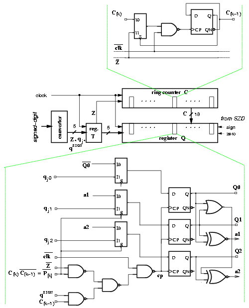
Figure 4.14: Convert-and-round unit for radix-8 divider
For the radix-8 divider, the 50 least-significant bits in the recurrence can be redesigned for low voltage. We can apply the dual-voltage technique also to the convert-and-round unit which is not in the critical path.
When applying dual voltage to the recurrence, the two cases with radix-2 and radix-8 CSA must be considered. As explained in Section 3.6, the time slack is longer for the radix-2 CSA implementation and the possible voltage V2 is lower. In particular for the radix-8 divider (critical path is 8.0 ns), we obtain the following values:
The values of Ediv indicated above take into account both the different number of flip-flops in register Wc and the voltage scaling in the convert-and-round unit.
It is clear that the implementation with radix-2 CSA is the most convenient for dual voltage. The reduction in d-v is about 30% with respect to l-p.
Because the synthesis of large circuits does not give results as good as manual design, we synthesized only the selection function using Synopsys Power Compiler. The synthesis of the selection function showed a critical path (through qL) of 3.0 ns (critical path for SEL in Passport/COMPASS implementation is 4.5 ns), while the path through qH was of 2.6 ns (3.6 ns for Passport/COMPASS). The energy reduction in the selection function, obtained by incremental compilation with power dissipation constraints was very little, about 5%.
Figure 4.15 shows the implementation of the low-power radix-8 divider and Table 4.4 summarizes the results obtained by applying the low-power techniques described above. We did not include in the table the estimation of a possible implementation with Synopsys Power Compiler because the reduction of energy in the selection function is less than 1% of the total.
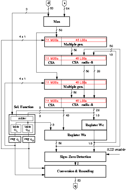
Figure 4.15: Low-power implementation of the radix-8 divider.
| standard | low-power | dual voltage | |
| blocks | nJ | nJ | (est.) nJ |
| control | 0.6 | 0.6 | 0.6 |
| clk tree | 0.4 | 0.4 | 0.4 |
|
mux | 1.4 | 0.2 | 0.2 |
| mul. gen. H | 3.1 | 2.2 | 1.1 |
| CSA H | 4.4 | 4.4 | 2.2 |
| mul. gen. L | 2.6 | 2.2 | 1.1 |
| CSA L | 6.0 | 4.8 | 2.4 |
| sel. func. | 3.6 | 4.6 | 4.6 |
| register Ws | 4.2 | 4.0 | *2.2 |
| register Wc | 4.2 | 1.2 | *2.0 |
| register qH | - | 0.2 | 0.2 |
| register qL | - | 0.2 | 0.2 |
|
SZD | 3.8 | 0.6 | 0.6 |
| C&R unit | 13.4 | 2.8 | *1.0 |
|
Total [nJ] | 47.5 | 28.5 | 19.0 |
| Ratio | 1.00 | 0.60 | 0.40 |
|
Area [mm2] | 2.2 | 1.8 | - |
| Values marked * include level shifters. | |||
Figure 4.16 shows the breakdown, as a percentage of the total, of the energy dissipated in the main blocks composing the unit.
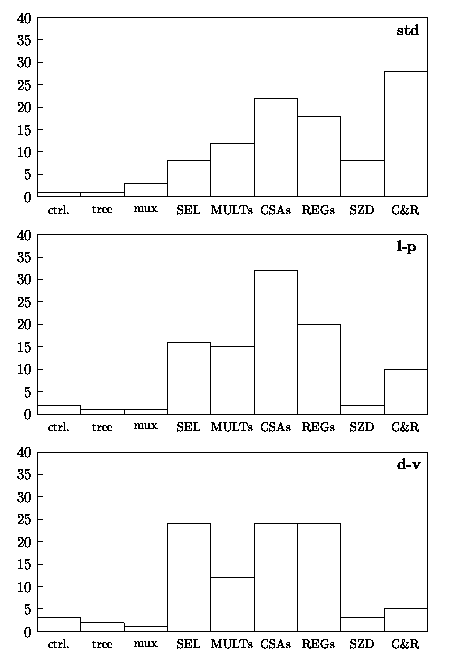
Figure 4.16: Percentage of energy dissipation in radix-8 divider.
In the l-p implementation the largest part of the energy is dissipated in the CSAs (more than 30%), while in the d-v estimate the largest portion is equally distributed (about 25% of the total for each block) among the two CSAs, the two registers W and the selection function.
In [34] a radix-8 divider is implemented by overlapping three radix-2 stages and computing the quotient digits in parallel. Moreover, the next partial remainder (ws and wc) is calculated speculatively for each possible quotient digit. This scheme, indicated here as r8overlap, is implemented in the Sun UltraSPARC FP-unit. As described in [34], the critical path is: 1 ×SEL + 2 ×CSA + 3 ×MUX
In order to compare the r8overlap division unit with our radix-8 divider, we made the following assumptions:
With these assumptions, we can reasonably estimate the pre-layout critical path of r8overlap as:
| SEL | + 2 CSA | + 3 MUX | + buff. | + reg. |
| 1.9 | + 1.6 | + 1.5 | + 0.7 | + 1.3 = 7.0 ns |
This is similar to the critical path (pre-layout) of the radix-8 unit described here:
| SEL(qL) | + mult | + HA | + reg | ||
| 3.8 | + 1.2 | + 0.5 | + 1.3 | = 6.8 ns. | |
| SEL(qH) | + mult | + HA | + FA | + reg | |
| 3.0 | + 1.2 | + 0.5 | + 0.8 | + 1.3 | = 6.8 ns. |
As for the area, Table 4.5 shows a comparison of the number of the wider (bitwise) blocks. Register QN in r8overlap can be eliminated by introducing register C. However it is not possible to change the representation of wC (e.g. reducing the size of register Wc) without penalizing the performance. Moreover, the resulting selection function of the overlapped implementation is about twice as large as the radix-8 SEL. In conclusion, it is reasonable to assume that the area of our divider is significantly smaller.
| r8overlap | radix-8 | |||
| no. CSAs | 6 | 2 | ||
| no. mux/mult | 6 | 2 | ||
| no. registers | 4 | (Ws, Wc, Q, QN) | 2.7 | (Ws, Wc/3, Q, C) |
We don't have data available on the energy consumption of the r8overlap division unit, but considering the larger area (larger current drawn) and roughly the same operation latency, we conclude that the energy dissipation is smaller in our implementation. Furthermore, the energy reduction techniques applied in the radix-8 divider might not be effective in the r8overlap scheme.
4 Smaller area implies smaller capacitance and usually reduced energy dissipation.