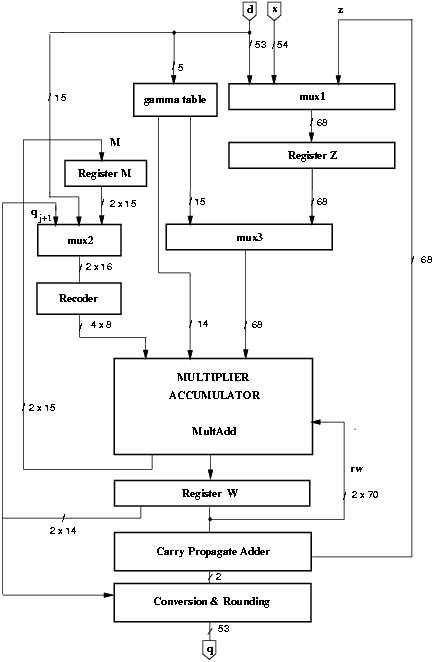
Figure 4.23: Block diagram of modified divider.
We now refresh some of the expressions of the radix-512 division algorithm presented in Chapter 2, The recurrence is implemented by
| (21) |
|
| (22) |
As for the other radices, d is normalized in [0.5, 1) and x < d. According to [32] the scaling factor M is in the range:
|
A first implementation of the divider is shown in Figure 2.4 on page pageref. Since the operations indicated in expression (4.5) and expression (4.6) are similar, they can be executed in the same unit. In [33] in order to reduce the area, the multiplier-accumulator required for the computation of M is eliminated, and the operation of expression (4.6) is executed in the main multiplier-accumulator. The modified block diagram is shown in Figure 4.23.

Figure 4.23: Block diagram of modified divider.

Figure 4.24: Cycles and operations.
Figure 4.24 shows the operation performed in the divider and the values stored in the registers during the different cycles.
Block gamma-table is a logic function which produces the two quantities -g1 and -g2 according to
|
|
The recoder is used to recode the multiplier into radix-4 representation with digits in the set {-2, -1, 0, 1, 2}.
Block MultAdd in Figure 4.23 executes both the multiplication and the addition in the recurrence. The multiple generator produces the partial products t0, t1, ¼, t7 and the adder reduces the number of the partial products to the final carry-save representation (9:2 adder). Summarizing, the MultAdd operations are:
|
In the scaling, the recoded multiplier is -M (15 bits).
|
In the recurrence, the recoded multiplier is qj+1 that is 11 bits (10 + 1 for sign) bits. In this case only 6 partial products are generated (t0-t5) and t6 and t7 are used to add the carry-save represented shifted residual rw[j].
|
The conversion block performs the conversion from the signed-digit quotient and the rounding. The carry-propagate adder is used to assimilate the carry save representation of Md = z and the final remainder. In addition, hardware to detect if the sum is zero (needed for the rounding) is provided in the carry-propagate adder.
The first implementation of the divider, which corresponds to the scheme of Figure 4.23, has a critical path of 10.5 ns (Figure 4.25) and a total execution time
|

Figure 4.25: Critical path (ns) for basic implementation.
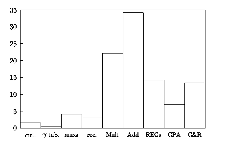
The energy dissipated by this standard implementation is reported in Table 4.11 and indicated in the column ßtandard". Figure 4.26 shows the percentage of energy dissipated in the blocks for the basic implementation of Figure 4.23.

Figure 4.26: Percentage of Energy dissipation in radix-512 divider.
For energy reduction in radix-512, we used a different approach than for the lower radices. From Figure 4.26, it is clear that most of the energy (about 60% of the total) is dissipated in the MultAdd block. This is not unexpected because MultAdd is the largest block and consists of several levels of CSAs. As a consequence, the distribution of the energy consumption is quite different from the dissipation in lower radices where, for example, the energy dissipation in the corresponding blocks (MULT and CSA) for radix-4 is less than 25% of the total. For this reason, many of the techniques presented in Chapter 3, which were developed for lower radices, are not very effective for the radix-512 divider.
Retiming by itself only reduces glitches at the input of MULT for lower radices, and in case of radix-512 retiming by itself is not much beneficial for MultAdd because the several levels of the tree of adders produce many glitches anyway.
Changing the redundant representation is a technique designed to reduce the energy dissipation in the registers by eliminating some flip-flops. Because it requires the propagation of the carry within a digit, this technique increase the energy dissipation in the adder, that however, for lower radices, does not offset the reductions obtained in the register. For radix-512, there is not sufficient time to propagate the carry in a log2 512 = 9 bit adder without increasing the critical path. The use of a radix-8 CSA (a radix-512 CSA could be decomposed in 3 radix-8 CSAs) might reduce the energy dissipated in the registers by about 2% of the whole energy consumption. But this reduction in the registers will be offset by the increase of glitches for the propagation of the carry in MultAdd.
Techniques such as equalizing the paths and using low-drive cells are not very effective for lower radices and are impractical for radix-512.
The techniques that can reduce significantly the energy dissipation in the radix-512 are the modification in the convert-and-round unit, disabling the CPA when not used, and using dual voltage in the recurrence to reduce the energy dissipated in MultAdd.
In addition to the techniques presented in Chapter 3, some work has been done in [45] to reduce the power dissipation in trees of adders. In [45], by using the redundancy in a 4:2 CSA (compressor), different configurations of the compressors are used to reduce the probability of transitions in the tree. However, experimental results in [45], showed that for a large tree of adders such as the one used in a 54 × 54 multiplier [7], the power savings are about 5%.
The first modification applied to the radix-512 divider is to disable the clock in flip-flops that do not change. This is particularly advantageous in register M and Z which change once and three times respectively, per division (Figure 4.24). The reduction in the energy dissipated is about 2.0 nJ corresponding to 3% of the total divider.
The carry-propagate adder (CPA) is used twice during the division. A first time to assimilate the value of z in the third cycle, and a second time in the last cycle to determine the sign of the remainder (and if it is zero). The CPA is switched off by forcing a constant logic value at its inputs when it is not used. The reduction in energy with respect to the basic implementation is about 5%.
In the basic implementation of the radix-512 divider, three registers (Q, QM, and QP) are necessary to store the partial quotient (r = 1). As explained in Section 3.10, the algorithm is modified as for lower radices, by eliminating the shifting of the digits previously loaded, the two registers QM and QP, and by recoding. Two additional registers are introduced: the 6-bit ring counter C to keep track of the digits to update and the temporary register T (10 bits) used in the recoding. The digit-decrementer, implemented both for the digits of Q and for register T, is a 9-bit ripple decrement-by-one circuit and its delay is about 4.0 ns. Note that the delay of the decrementer does not affects the critical path.
By implementing the modified algorithm in the convert-and-round unit, we reduce the number of flip-flops in the unit from 162 (registers Q, QM, QP) to 70 (registers Q, C, T). The energy consumption in the divider is reduced by about 10%.
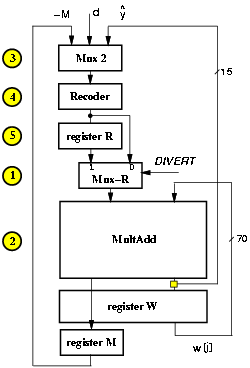
As mentioned above, for radix-512 the purpose of retiming is to limit the critical path to a few bits and use dual voltage. In order to do so, we have to move the operations done on the MSBs (selection in mux2 and recoding) from the beginning of the cycle to the end of the cycle. This can be done as sketched in Figure 4.27.b by introducing an extra register to store the carry-save representation of the recoded operand.

Figure 4.27: Retiming of the recurrence.
However, the scheme of Figure 4.27 requires an additional initialization cycle to store in register R the recoded value of d15 (dREC). An alternative to the addition of the extra cycle is to take advantage of the fact that in cycles 2 and 3 the value to be recoded is the same (-M). In this case we can use a multiplexer to divert to MultAdd either the output or register R or directly the output of the recoder, as shown in Figure 4.28. This multiplexer (Mux-R) is controlled by a new signal DIVERT, set by the controller, that routes the MultAdd input signals. Table 4.10 shows the values of the signals in the unit in the first 4 cycles. Note that blocks Mux2 and Rec are replicated in the table for clarity.
| cycles | ||||
| 1 | 2 | 3 | 4 | |
| REG M | - | -M | -M | -M |
| REG W | - | - | Md | w[0] |
|
Mux2 | d | -M | ||
| Rec | dREC | -MREC | ||
|
REG R | - | - | -MREC | [^y][1]REC |
| Mux-R | dREC | -MREC | -MREC | [^y][1]REC |
| MultAdd | -M | Md | w[0] = Mx | w[1] |
|
Mux2 | [^y][1] | [^y][2] | ||
| Rec | [^y][1]REC | [^y][2]REC | ||
| DIVERT | 0 | 0 | 1 | 1 |

Figure 4.28: Retimed recurrence with Mux-R.

Figure 4.29: Critical path (ns) after retiming.
The new multiplexer Mux-R is now on the critical path and the clock cycle must be lengthed to accommodate the additional 0.5 ns of its delay. The new critical path is shown in Figure 4.29. However, the solution with Mux-R is still advantageous over the solution with an extra cycle. In fact, the number of cycles for the radix-512 division (10) is quite small and the longer clock cycle increases the execution time by about 5 ns that is still a shorter time than one extra clock cycle required for the first solution.
After the retiming the 52 LSBs of MultAdd and register W can be redesigned for dual voltage. The time slack for those 52 LSBs is 4.3 ns that allows a minimum dual voltage V2 = 2.3 V.
Furthermore, voltage can be also scaled in the convert-and-round unit resulting in reduction of energy dissipated of 40% with respect to the basic implementation of the divider.
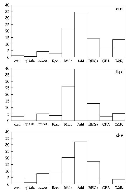
For the radix-512 divider, the retiming increases the critical path by about 5%. Because we want to reduce the energy without penalizing the performance, in this case, there is a tradeoff between smaller energy and longer delay. Since, as previously discussed, the only technique which reduces significantly the energy consumption in the recurrence is the use of dual voltage, we decided not to apply the other techniques (change redundant representation, using low-drive cells, etc.) and give up performance for small energy reductions. Table 4.11 reports the energy values for the three implementations:
Optimization with Synopsys Power Compiler was not performed because in the radix-512 divider the selection of the quotient digit is done by rounding.
Figure 4.30 shows the breakdown, as a percentage of the total, of the energy dissipated in the main blocks composing the unit.
| standard | low-power | dual voltage | |
| blocks | nJ | nJ | (est.) nJ |
|
control | 1.0 | 1.0 | 1.0 |
| clk tree | 0.5 | 0.5 | 0.5 |
|
g table | 0.4 | 0.4 | 0.4 |
| mux 1 | 1.1 | 1.1 | 1.1 |
| mux 2 | 0.6 | 0.6 | 0.8 |
| mux 3 | 1.1 | 1.1 | 1.1 |
| recoder | 2.0 | 2.0 | 3.8 |
| Mult | 14.5 | 14.5 | 8.0 |
| Add | 22.5 | 22.5 | 12.5 |
| registers W | 6.6 | 5.5 | *3.6 |
| register M | 0.5 | 0.3 | 0.3 |
| register Z | 2.3 | 1.5 | 1.5 |
| reg. R + mux-R | - | - | 1.1 |
|
CPA | 4.5 | 1.5 | 1.5 |
| C&R unit | 8.7 | 2.7 | *1.3 |
|
Total [nJ] | 66.5 | 55.0 | 38.5 |
| Ratio | 1.00 | 0.85 | 0.60 |
|
Area [mm2] | 6.0 | 6.4 | - |
| Tcycle [ns] | 11.0 | 11.0 | 11.5 |
| tdiv [ns] | 110 | 110 | 115 |
| Values marked * include level shifters. | |||

Figure 4.30: Percentage of energy dissipation in radix-512 divider.