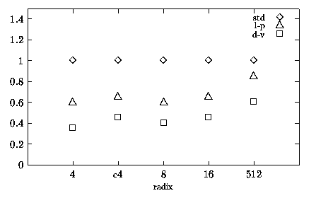
Figure 5.1: Reduction in E
In this chapter we provide an overview of the implementations presented in Chapter 4 and comment on the results obtained and on the effectiveness of the techniques.
The impact of the techniques used in the design of low-power division and square root units is summarized in Table 5.1, where they are evaluated in terms of costs and benefits on the three main design constraints: delay, energy and area. For the delay, the cost represents an increase in the critical path and the benefit a reduction in it. For the area the cost and benefits are increase and reduction in the area, whereas for the energy, Table 5.1 lists only the benefits: reduced energy dissipation. The symbol "-" in table means that the corresponding cost/benefit is not affected by that technique. In addition to the traditional design constraints, Table 5.1 also reports the cost in terms of "man-power", which is a measure of the design time needed to implement the technique in question.
| technique | delay | area | man-power | energy | ||
| cost | benefit | cost | benefit | cost | benefit | |
| retiming | - | low | low | - | high | low |
| red. in mux | med. | - | - | - | low | high |
| change repr. | - | - | - | high | med. | high |
| low-drive gates | - | - | - | low | low | med. |
| dual voltage | - | - | high | - | med. | high |
| paths equaliz. | - | - | - | - | high | low |
| SEL partition | high | - | med. | - | med. | high |
| glitch filter | high | - | med. | - | med. | med. |
| C&R algo mod. | - | - | - | high | high | high |
| gated clock | - | - | med. | - | high | med. |
| gated tree | - | - | low | - | med. | med. |
| disable blocks | - | - | high | - | low | high |
|
| ||||||
It is worth reminding the reader that the results presented in this work are derived from experience in the design of arithmetic units using static CMOS standard cell libraries and automatic floor-planning. By implementing the units in question with different technologies (dynamic CMOS, GaAs, etc.) or using full-custom layout styles, results may be different.
A description of the tradeoffs for each of the techniques presented in Chapter 3 follows.
The retiming the recurrence is probably the most important and effective technique. Although the benefits of the retiming in itself are moderate, especially for high radices when the increased glitches in the selection function offset the reductions in the multiple generator and carry-save adder, the retiming allow the "decoupling" of the most-significant bits which are on the critical path from the rest of the bits that can be redesigned for low power by applying the other techniques.
The design effort is quite high especially for high radices (radix 8, 16 and 512) in which the retiming alters the critical path.
This modification is relatively easy to implement and gives good reductions in the multiplexer, although it has a smaller impact on the whole unit. However, additional work has to be done by skewing the select signal to avoid that the delay of the multiplexer becomes a part of the critical path.
Changing the redundant representation has a high impact on both the energy dissipated and the area. The higher the radix, the higher is the benefit. The tradeoff is that propagating the carry inside the digit increases the number of transitions in the CSA. However, if registers are implemented with edge-triggered flip-flops the extra transitions in the CSA do not offset the reductions in the registers. The critical path is not affected by this techniques unless the delay of the radix-r CSA is too long (e.g. for radix-512).
Replacing gates not in the critical path with gates which consume less power is relatively easy and can achieve high reductions in the overall energy dissipation. Unfortunately the application of this technique depends highly on the library used. In our library (Passport) the cells with low-drive capability were very limited and the use of this technique not very effective.
The use of dual voltage gives probably the highest reduction in the energy consumption because by reducing the voltage the energy decreases quadratically. However, each library is guaranteed to work properly in a given range of power supply voltage (for example library ST CB45000 can operate with voltage between 3.6 - 2.7 V) and sometimes the optimal lower voltage V2 cannot be implemented. Dual voltage requires level-shifters to interface the lower voltage parts with the portions of the circuit at higher voltage. Moreover, in a dual voltage unit the power grid must accommodate three different voltage levels (VDD, V2 and VSS) and this might complicate the layout of the chip.
This technique was only adopted in the implementation of the radix-4 divider. It was abandoned in the realization of the other units because the design effort was too high in relation to the benefits. We used automatic floor-planning for the layout to have a fast turn-around time in the realization of many versions, incrementally improved, of the same unit. With automatic floor-planning the cells are placed randomly and the delay due to interconnections is different for each layout. As a consequence, it is impossible to really equalize the paths and the glitches cannot be completely eliminated.
As already mentioned in Section 3.8, the partitioning of the selection function affects the critical path. However, if the clock period is long enough to accommodate the additional time required, the energy reduction is quite significant especially for high radices.
This modification affects the critical path if filtering is positioned at the input of the selection function. This is done for high radices in the retimed implementation. The filtering devices (multiplexers) always increase the area and an extra signal to enable the filter (select input in the multiplexer) has to be generated. Moreover, the technique can be applied to any part of the circuit not in the critical path, where a large number of glitches have to be suppressed, without any penalty on the latency on the unit. However, many select signals require a fine-tuning of the timing of the circuit that could result very hard to implement.
The modification in the on-the-fly conversion and rounding algorithm brought significant reductions in energy in the convert-and-round unit. The latency of the unit increases with the radix because a digit might be decremented and this is done with a carry-propagate decrementer within a digit. But because the convert-and-round unit is not in the critical path, the modified algorithm can be applied to all the radices (4 through 512) without affecting the performance of the division or square root unit.
This technique is used in the convert-and-round unit not only to reduce the energy dissipated in the flip-flops, but also to allow the loading of the digit in the correct position without the use of a multiplexer. In general, the addition of one or more gates to the clock pin of a flip-flop increases the latency of the circuit. However, in our designs this is only done for registers not in the critical path.
For this technique apply the same considerations done for the clock-gating: if the tree is on the critical path, adding a gate increases the latency of the unit. This is not the case of the trees to distribute the signals in the convert-and-round unit, where a significant reduction of the energy dissipated in the unit is achieved.
Switching off a block not used for several cycles is probably the easiest modification to implement. However, the block has to be disabled by introducing additional logic gates which increase the area and affect the delay of the unit if the block is on the critical path. The reductions in the energy dissipated are higher for units in which the ratio
|
The experimental results presented in [15] claim that synthesis with Synopsys Power Compiler reduces the power dissipated by about 11% on the average (peak of 66%) for some industrial benchmarks and all the delay constraints are met.
In our small experiment the results obtained are good for relatively small circuits (case of selection functions), while for larger and more complex circuits (radix-4 divider recurrence) not only the power is not reduced much, but also the initial design, optimized for smaller delay, is not as good as attainable by manual design.
For these reasons, we conclude that the use of Synopsys Power Compiler is helpful in solving optimization problems of small functional blocks, but not very effective in reducing delay and power in larger and more complex blocks, such as a divider.
Table 5.1 shows that the modifications done at an higher level of abstraction, such as algorithm modification or change of the encoding, have a larger impact on the energy dissipated than techniques applied a lower level, such as path equalization or glitch filtering. Furthermore, modifications done at higher level of abstraction are more independent of the technology and tools used.
| Ediv [ nJ ] | Area [ mm2 ] | Tcycle | cycles | tdiv | |||||
| std | l-p | d-v | std | l-p | [ns] | [ns] | |||
|
radix-4 | 45.5 | 26.0 | 16.0 | 1.4 | 1.2 | 7.0 | 30 | 210 | |
|
| ratio | 1.00 | 0.60 | 0.35 | speed-up 1.0 | ||||
|
combined | 46.0 | 29.5 | 20.0 | 1.9 | 1.8 | 7.3 | 29 | 210 | |
| radix-4 | ratio | 1.00 | 0.65 | 0.45 | |||||
|
radix-8 | 47.5 | 28.5 | 19.0 | 2.2 | 1.8 | 8.0 | 20 | 160 | |
|
| ratio | 1.00 | 0.60 | 0.40 | speed-up 1.3 | ||||
|
radix-16 | 46.0 | 30.0 | 22.0 | 2.2 | 1.8 | 9.2 | 16 | 150 | |
|
| ratio | 1.00 | 0.65 | 0.45 | speed-up 1.4 | ||||
|
radix-512 | 66.5 | 55.0 | 38.5 | 6.0 | 6.4 | 10.5 | 10 | 105 | |
|
| ratio | 1.00 | 0.85 | 0.60 | speed-up 2.0 | ||||
Table 5.2 summarizes the results obtained for energy-per-division, area and execution time (tdiv = Tcycle × cycles) for the implementations of Chapter 4. Note that for the combined division/square root unit the number of cycles is one less than for the division only unit. This is due to the different initialization cycle in the two implementations. However, it is possible to change the initialization in the radix-4 divider and reduce the number of cycles to 29. For the implementations of Table 5.2, as the radix increases the cycle time Tcycle is longer, but the number of cycles is reduced, and the resulting execution time is shorter. The speed-up, relative to the radix-4 implementation, is the ratio of the execution times
|

Figure 5.1: Reduction in E
The main goal of this research work is to reduce the energy consumption in division and square root units without penalizing the performance. Figure 5.1 shows, for each radix, the reductions in the energy dissipation with respect to the ßtandard" (std; symbol \Diamond in figure). Label c4 in tables indicates values obtained for the radix-4 combined division and square root unit. For all the radices, with the exception of radix-512, the reduction in energy is around the 60% level for the low-power implementation (l-p; symbol \triangle in figure), and about 40% for a possible implementation with dual voltage (d-v; symbol [¯] in figure). However, also for the radix-512 divider there is a reduction, although it is smaller.
We now briefly comment on the percentage of energy dissipated in the blocks composing the units, which were presented in Chapter 4. In blocks such as control unit (ctrl) and clock distribution tree (tree), in which energy is not reduced going from the std to the d-v implementation, although the values of energy in nJ are not changed, the percent contribution to the overall energy dissipation increases. For all radices and schemes, the reductions obtained in the convert-and-round (C&R) unit and by disabling the sign-and-zero detection (SZD) block are quite evident. Blocks in the critical path tend not to reduce their percent contribution to the overall dissipation. In the case of the selection function (SEL), because no techniques are effective to reduce energy without penalizing the critical path, for all the radices there is a percent increase going from the std to the d-v implementation. This is particularly evident for radix-16 (Figure 4.22 at page pageref) where the same energy value for SEL contributes to the 27% of the total of l-p and to the 37% of d-v. Moreover, for the selection function, due to the increased complexity of the function, the percent contribution to the total grows with the radix: from 11% for d-v radix-4 to 37% for d-v radix-16. As the radix increases the larger contribution migrates from the registers to the selection function and the hardware to perform the addition (CSAs for radix-8 and 16, Mult and Add for radix-512).
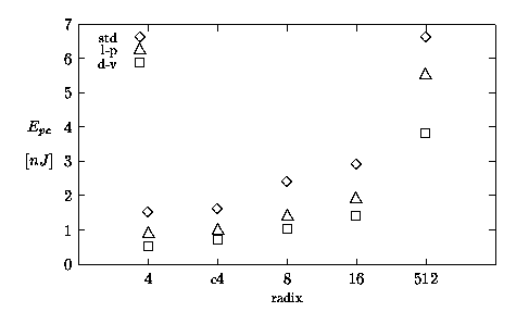
Figure 5.2 and Figure 5.3 show the values of energy-per-division (Ediv) and energy-per-cycle (Epc), respectively, expressed in nJ. It is interesting to note that, with the exception of radix-512, the units dissipate roughly the same energy to perform a division (Figure 5.2). On the other hand, Figure 5.3 shows that the energy-per-cycle increases with the radix. As it happens for the execution time, the smaller number of cycles for higher radices compensates the higher Epc in Ediv = Epc × cycles. However, while for the latency there is a speed-up for higher radices, for energy dissipation there is no improvement.

Figure 5.2: Energy-per-division: summary.

Figure 5.3: Energy-per-cycle: summary.
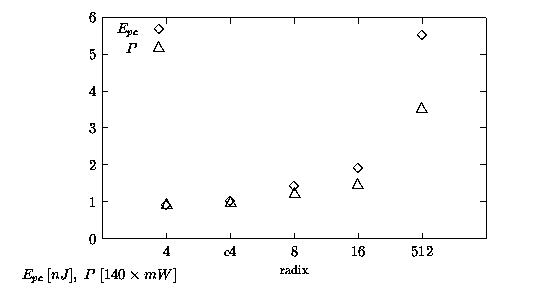
Dividing the values of Epc by Tcycle (see expression (1.1)) we obtain the average power dissipation
|

Figure 5.4: Energy-per-cycle and scaled average power for
If for a processor low energy is the priority, like for portable electronics where the life time of batteries depends on Ediv, a high-radix divider with a lower power supply voltage (VDD) and a reduced speed can be used in place of a lower radix divider with same latency. For example, using the data of Table 5.2, a divider with latency of 210 ns can be implemented either with a radix-4 (Ediv = 26 nJ), or with a radix-16 powered at VDD = 2.5 V which dissipates about Ediv = 18 nJ, reducing by one third the energy consumption.